Apply Scale in Blender: apply the scale first when Bevel or thickness looks wrong
What Apply Scale does in Blender, and how an unapplied scale from Object Mode makes Bevel width and Solidify thickness uneven, shown with before and after screenshots using the same values. Also covers the Ctrl+A menu items, the difference from Alt+S, and what to watch for with negative scale and shared mesh data.
한국어English
ON THIS PAGE
Based on: Blender 5.2 LTS (screenshots from 5.2.1, English interface, default shortcuts). Checked in November 2026. All pictures are real Blender screenshots. The red numbers, boxes and red labels were added to explain them. Steps that have no picture follow the official Blender 5.2 manual and the default keymap.
You stretch a box with S and add a Bevel modifier, and only the long edges get a wide bevel. You give a shell some thickness with Solidify, and each wall has a different thickness. You typed one value, yet the result changes with direction. Most of the time the cause is an unapplied scale.
This guide puts before and after applying the scale side by side with the same values. Then it covers the Ctrl+A menu, how it differs from Alt+S, and when to be careful.
After this guide you can:
- Read the Scale values in the Object tab and tell whether the scale is unapplied.
- Apply the scale with
Ctrl+A‣ Scale. - Tell applying the scale apart from
Alt+S(clearing it). - Know the cases that need care, such as negative scale and mesh data shared by several objects.
1. What applying the scale means
A Blender object is made of shape data (the mesh) plus location, rotation and scale values on top of it. When you press S in Object Mode, the mesh points stay where they are and only the Scale value changes. The object looks bigger, but the mesh itself still "thinks" it has its original size.
Think of a drawing on a rubber sheet. Pull the sheet to one side and the drawing looks stretched, but let go and it goes back. Apply Scale redraws the stretched picture onto a fresh sheet of paper. The shape stays the same and the stretch value goes back to 1.
| Before applying | After applying | |
|---|---|---|
| Shape on screen | Stretched | Same |
| Scale in the Object tab | Values like 2, 1, 1 | 1, 1, 1 |
| Real size (Dimensions) | 4 m × 2 m × 2 m | Same |
| Mesh point coordinates | As before stretching | Moved by the stretch |
Most modifiers calculate with the mesh's own coordinates (local coordinates) and multiply by the object's scale at the end. So when the scale differs by direction, the modifier result is stretched differently by direction too. Sections 2 and 3 show this.
2. When Bevel is wider on one side
Beginner chapter 7, section 7, covers the same example in an orthographic view. This section looks at the same values in a perspective view and puts the before and after side by side.
Starting point: The default cube in a new file (File ‣ New ‣ General).
Steps:
- With the cube selected and the mouse over the 3D Viewport, press
S→X→2→Enter. The cube becomes twice as long along X. - Look at Scale in the Object tab (orange square icon) of the Properties editor. It is X
2.000, Y and Z1.000(Figure 1). - In the Modifier tab (wrench icon), choose Add Modifier ‣ Generate ‣ Bevel.
- Set the Bevel Amount to
0.5and Segments to3(Figure 2).
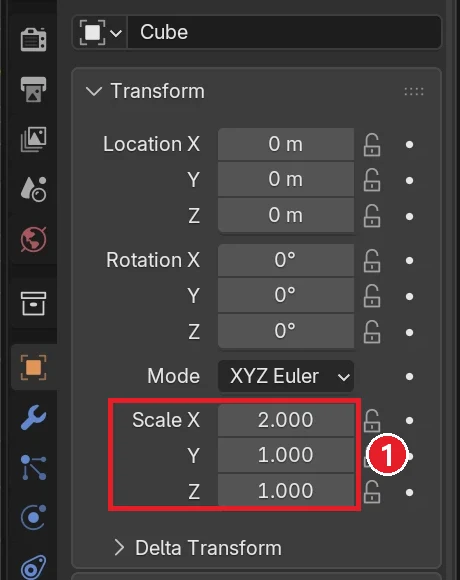 Figure 1. Scale not applied. ① Scale X 2.000, Y and Z 1.000 (Blender screenshot)
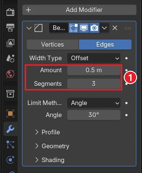 Figure 2. Bevel values. ① Amount 0.5 m, Segments 3 (Blender screenshot)
The left side of Figure 3 shows this state. The edges at the long (X) ends are beveled wider than the side edges. The Amount of 0.5 m is calculated at the mesh's original size and then stretched twice along X. Seen from above, the same edge is cut about 1 m across and 0.5 m deep.
Steps (the fix):
- With the mouse over the 3D Viewport, press
Ctrl+A. The Apply menu opens (Figure 5 in section 4). - Choose Scale.
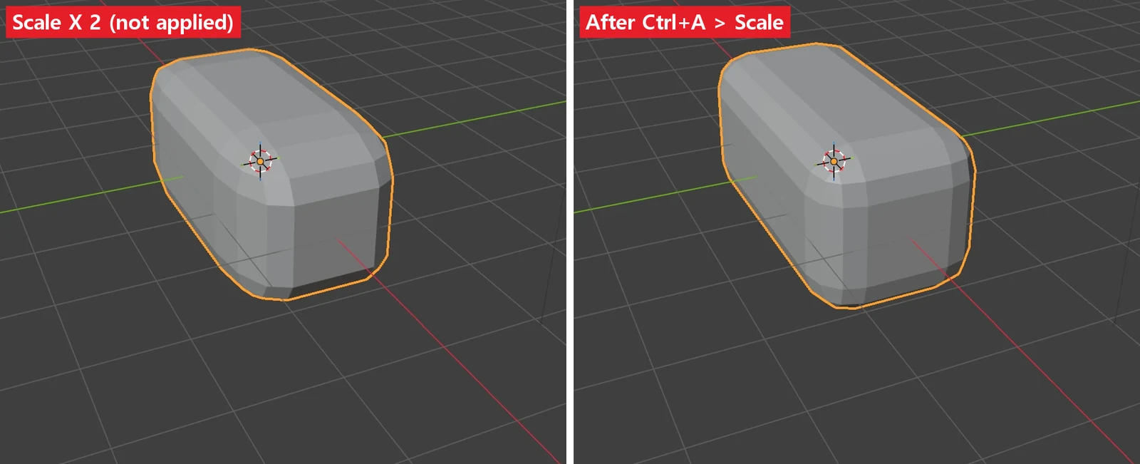 Figure 3. The same Bevel (Amount 0.5 m, Segments 3). Left: before applying the scale. Right: after
Ctrl+A ‣ Scale (Blender screenshot)
As on the right of Figure 3, every edge now has the same bevel. No Bevel value changed. Scale in the Object tab becomes 1.000 for X, Y and Z, and the box is still 4 m × 2 m × 2 m. You can see the real size under Dimensions in the Item tab of the sidebar (N).
Other Bevel settings (Limit Method, weights) are covered in the Bevel modifier guide.
3. When Solidify walls differ in thickness
The same thing happens with thickness. Figure 4 looks down in Wireframe on a box with its top removed, stretched three times along X, with Solidify (Thickness 0.2 m, Offset -1).
Starting point: The "box with the top removed" from section 1 of the Solidify modifier guide. If you do not have it, switch the default cube to Edit Mode (Tab), select the top face, delete it with X ‣ Faces, and press Tab again.
Steps:
- In Object Mode, press
S→X→3→Enterto stretch the box three times along X. - In the Modifier tab, add Add Modifier ‣ Generate ‣ Solidify and set Thickness to
0.2. - Look from above with numpad
7and switch toZ→ Wireframe. The left and right walls are thicker than the top and bottom walls (left of Figure 4). - With the mouse over the 3D Viewport, choose
Ctrl+A‣ Scale. All four walls get the same thickness (right of Figure 4).
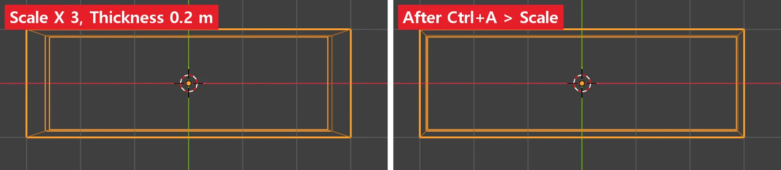 Figure 4. The same Solidify (Thickness 0.2 m). Left: before applying (Scale X 3). Right: after applying (Blender screenshot)
When measurements matter, such as wall thickness for 3D printing, this difference ends up in the real object. Apply the scale before you measure thickness.
4. The Ctrl+A menu at a glance
Ctrl+A opens the Apply menu in Object Mode when the mouse is over the 3D Viewport. It is the same menu as Object ‣ Apply in the header.
Steps: Select an object, keep the mouse over the 3D Viewport and press Ctrl+A. If you only want to look, close it with Esc.
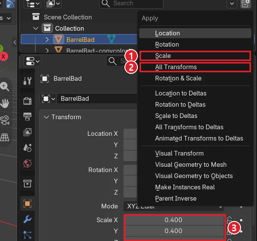 Figure 5. The Apply menu. ① Scale ② All Transforms ③ A scale not yet applied (the picture shows a different object with Scale 0.4, 0.4, 0.5) (Blender screenshot)
| Menu item | What it does | Common use |
|---|---|---|
| Location | Makes the current location the zero point. The origin moves to the world origin (0, 0, 0) | Rarely |
| Rotation | Makes the current rotation 0° | Using a tilted model as the upright reference |
| Scale | Makes the current size 1 | Before adding modifiers, before exporting |
| All Transforms | Location, rotation and scale at once | Before exporting to a game engine or 3D printing |
| Rotation & Scale | Only rotation and scale | When the location should stay |
| … to Deltas | Moves values into the Delta Transform fields | Layering animation on top |
| Visual Transform | Bakes the position made by constraints into the values | Before removing a constraint |
| Visual Geometry to Mesh | Bakes the modifier result into the mesh | Finalizing all modifiers |
The menu names and what they do match the Apply page of the Blender 5.2 manual. This guide is about the Scale row.
Watch where the mouse is. If the mouse is over a modifier panel in the Properties editor when you press Ctrl+A, Blender does not open the Apply menu. It applies that modifier instead: the modifier disappears and its result is baked into the mesh. If that happens, press Ctrl+Z, move the mouse over the 3D Viewport and try again.
5. Apply Scale is not Alt+S
Alt+S (Clear Scale) has a similar name but the opposite result.
Ctrl+A ‣ Scale (apply) | Alt+S (clear) | |
|---|---|---|
| Scale value | Becomes 1 | Becomes 1 |
| Shape on screen | Stays the same | Goes back to before the stretch |
| Use it when | You want the current shape as the reference | You want to undo the stretch |
In the rubber-sheet picture, applying redraws the stretched drawing on new paper, and clearing lets go of the sheet so it springs back.
6. Cases that need care
The cases below follow the Blender 5.2 manual and the operator description. They are not shown in this guide's pictures.
Negative scale: A negative scale such as S → X → -1 mirrors the object. Applying it can flip the front and back of the faces (the normals), which makes the shading look wrong. In Blender 5.2, applying the scale has a Corrective Flip Normals option that prevents this, and it is on by default. Right after applying, you can see it in the Adjust Last Operation panel at the lower left of the 3D Viewport. If faces look black, check the face direction. How to see face direction is in Checking a model before 3D printing.
Shared data: When several objects use one mesh, like objects duplicated with Alt+D, Blender asks for confirmation when you apply the scale. The data has to become single user (one object only) first. After that, editing one object no longer changes the other.
Text and curves: If Apply Properties in the Adjust Last Operation panel is on (the default), applying the scale also adjusts properties such as font size and curve thickness.
Armatures and animation: Apply transforms before rigging and animation, because applying them to an armature does not change pose locations or animation curves.
7. When to apply the scale
| When | Why |
|---|---|
| Before adding modifiers like Bevel, Solidify or Array | Prevents the mismatch in sections 2 and 3 |
| Before exporting to a game engine or a 3D printer | Fewer surprises with scale values in the other program |
| Before rigging and animation | The manual's advice in section 6 |
| When you only changed the size in Edit Mode | No need to apply. Edit Mode changes the mesh itself, so Scale stays 1 |
Export checks are covered in Rules for game-ready 3D assets and Moving a Blender model to Godot.
8. Exercises
- Flatten the default cube with
S→Z→0.5and add Bevel (Amount0.3). See whether the top and bottom edges or the side edges are beveled less, then check that they match afterCtrl+A‣ Scale. - On the same cube, press
Alt+Sinstead ofCtrl+A‣ Scale. Write down what happens to the shape. - In Edit Mode (
Tab), select all withAand stretch withS→X→2. Go back to Object Mode and check the Scale value in the Object tab.
9. Common mistakes and fixes
| Symptom | Cause | Fix |
|---|---|---|
| The bevel width differs by direction | The scale from Object Mode was not applied | Ctrl+A ‣ Scale over the 3D Viewport (section 2) |
| Solidify walls differ in thickness | Same cause | Ctrl+A ‣ Scale (section 3) |
The modifier disappeared after Ctrl+A | The mouse was over the modifier panel | Ctrl+Z, then try again with the mouse over the 3D Viewport (section 4) |
| Setting Scale to 1 made the object smaller | Alt+S (clear) was pressed | Ctrl+Z, then Ctrl+A ‣ Scale (section 5) |
| A confirmation appears when applying | The mesh is shared with another object | Continue if splitting is fine, cancel if they must stay linked (section 6) |
| Faces look black after applying | A negative scale flipped the face direction | Check face direction and fix it (section 6) |
Summary
If you changed the size in Object Mode, put the mouse over the 3D Viewport and press Ctrl+A ‣ Scale before modifiers and exporting. The next guide shows how to find and fix texture paths when a material turns pink.
Previous: Moving the origin in Blender · Next: When a material turns pink
References
- Blender 5.2 Manual: Apply (Apply menu, Corrective Flip Normals, Apply Properties)
- Blender 5.2 Python API: bpy.ops.object.transform_apply (option defaults)
- Related: Blender beginner chapter 7: modifiers, Solidify modifier
- Shortcuts: default (Blender) keymap of Blender 5.2.1.
- Pictures: screenshots made in Blender 5.2.1 while writing this site's Blender guides.