Bevel modifier: round edges, and only the ones you want by angle or weight
Round edges with Amount and Segments in the Bevel modifier, choose which edges to bevel with the Angle and Weight limit methods, and see how Clamp Overlap keeps the shape clean when the bevel is too wide, using the default cube and a cylinder.
한국어English
Based on: Blender 5.2 LTS (screenshots from 5.2.1, English interface, default shortcuts). Checked in November 2026. All pictures are real Blender screenshots. The red numbers and boxes were added to explain them. The Properties editor was dragged wider.
Real objects almost never have razor-sharp edges. A desk corner or a phone frame is always a little round. Cutting a 3D model's edges a little lets light catch them, and the model looks much more real. The Bevel modifier does this without touching the original shape.
Think of a woodworking plane. You decide how deep to cut (Amount), in how many passes to round it (Segments) and which edges to cut (Limit Method). Unlike a real plane, you can change a number and the cut starts over.
After this post you can:
- Set the bevel width and roundness with Amount and Segments.
- Bevel only sharp edges with the Angle limit method.
- Bevel only chosen edges with Edge Bevel Weight and the Weight limit method.
- Tell what Clamp Overlap prevents.
Before you start: Start from the default cube in a new file (File ‣ New ‣ General). Select the cube and open the Modifiers tab (wrench icon) in the Properties editor. A first try of Bevel is in section 4-1 of Blender beginner chapter 7. This post covers the settings after that.
1. Add Bevel and see the defaults
Follow along: In the Modifiers tab, click Add Modifier → Generate → Bevel. You can also open the menu and type B E V (section 5 of Every Blender modifier in one list).
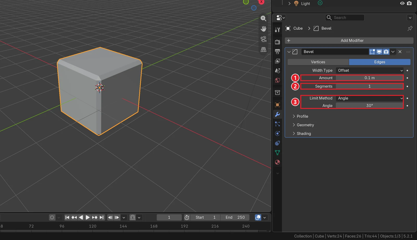 Figure 1. Right after adding it: ① Amount 0.1 m ② Segments 1 ③ Limit Method Angle, Angle 30°. Each edge gets one slanted strip, so the faces go from 6 to 26 (Blender screenshot)
| Field | What it does | Default |
|---|---|---|
| Vertices / Edges | Bevel the edges, or only around the corner points | Edges |
| Width Type | How Amount is measured: Offset, Width, Depth, Percent, Absolute | Offset |
| Amount | How wide the cut is | 0.1 m |
| Segments | How many strips the cut is split into. More is rounder | 1 |
| Limit Method | Which edges to bevel: None, Angle, Weight, Vertex Group | Angle |
| Angle | The angle used when Limit Method is Angle | 30° |
| Profile | Whether the cut is concave or convex (Shape), or a custom profile | Collapsed |
| Geometry | How meeting edges are handled, Clamp Overlap (section 4) | Collapsed |
| Shading | Harden Normals and other shading options | Collapsed |
2. Round it: Amount and Segments
With Segments 1, the edge is just a slanted strip. Split it into more strips to make it round.
Starting point: The cube with Bevel from the previous section.
Follow along:
- Set Amount to
0.2. - Set Segments to
3.
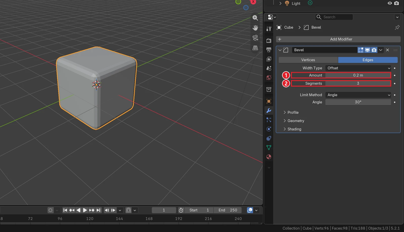 Figure 2. ① Amount 0.2 m ② Segments 3. Each edge is split into three strips and looks round; the cube now has 98 faces (Blender screenshot)
More Segments means rounder edges, but faces add up quickly. Raise it only until it looks round on screen. For objects seen from a distance, 2 or 3 is often enough.
If the cut looks faceted, click Object ‣ Shade Smooth in Object Mode, or turn on Harden Normals in the Shading panel. Harden Normals makes the bevel strips look smooth while large flat faces still look flat, by adjusting the normals (the direction each face points).
3. Choose which edges: Angle and Weight
3-1. Limit Method Angle: only sharp edges
The default Angle 30° means "bevel only edges where the two faces meet at more than 30°". Every cube edge is 90°, so they were all cut. You see the difference on round objects.
Starting point: Delete the cube. With the cube selected and the mouse over the 3D Viewport, press X → Delete, then add a cylinder with Add ‣ Mesh ‣ Cylinder.
Follow along:
- Add a Bevel to the cylinder in the Modifiers tab and set Amount to
0.1and Segments to3. - Set Limit Method to None.
- To see the cut lines, open Viewport Overlays (the down arrow next to the two overlapping circles at the right of the 3D Viewport header) and turn on Wireframe. Left-click an empty spot to deselect.
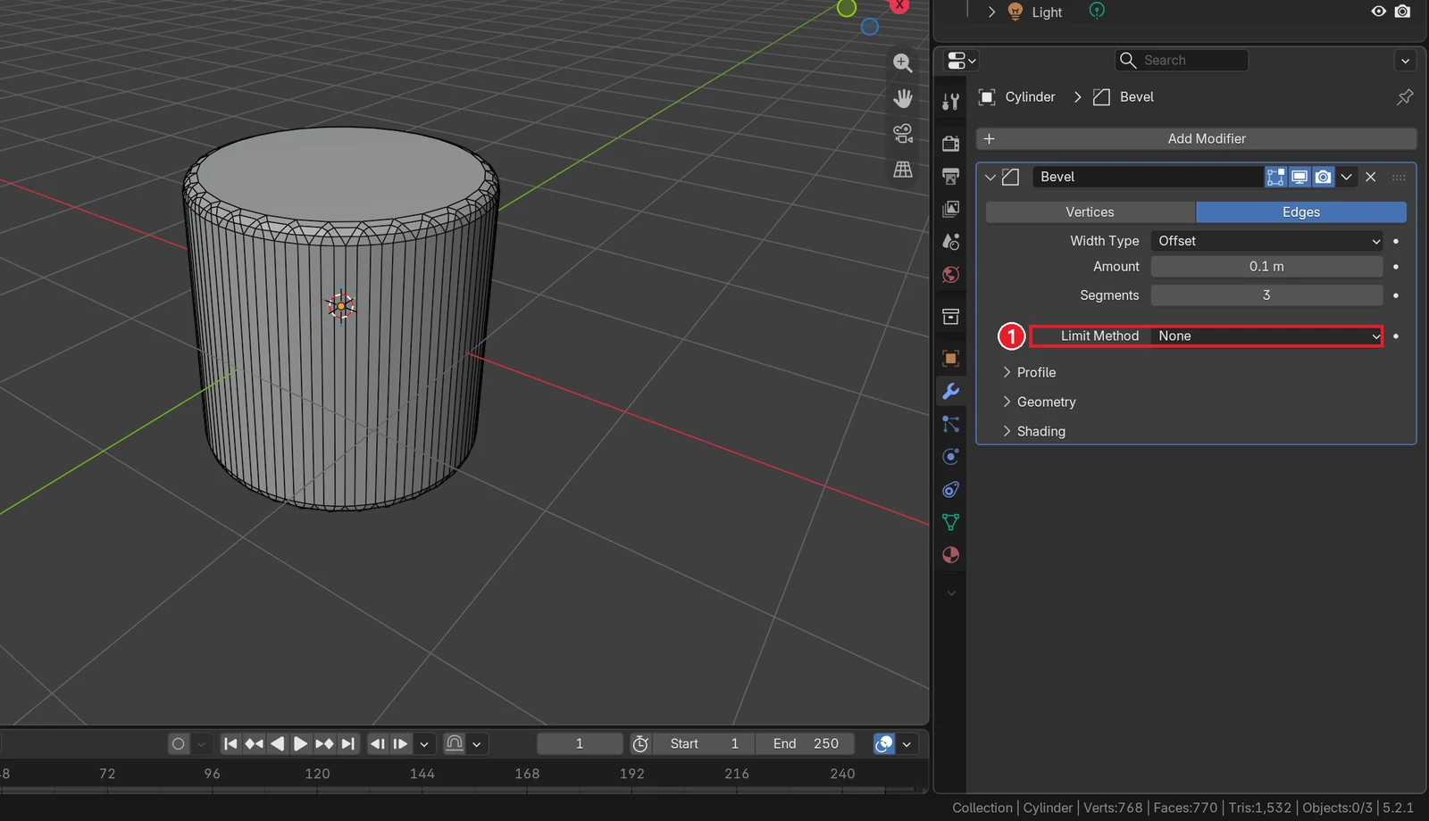 Figure 3. ① Limit Method None: even the vertical side lines are cut, so lines crowd the side. 768 points, 770 faces (Blender screenshot)
- Set Limit Method back to Angle.
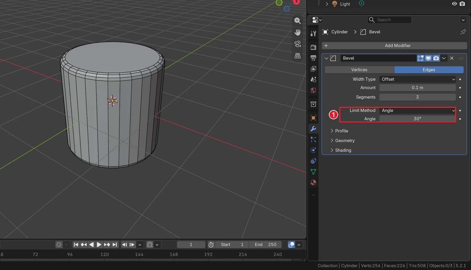 Figure 4. ① Limit Method Angle (30°): only the top and bottom rims, bent at 90°, are cut. The side lines, bent only 11.25° each, are not. Points drop from 768 to 256 (Blender screenshot)
The cylinder side has 32 pieces, so neighboring faces bend only 360 ÷ 32 = 11.25°. That is gentler than 30°, so Angle skips them. Leaving smooth curves alone and cutting only real edges is why Angle is the default.
3-2. Limit Method Weight: only the edges you pick
Often an angle can't separate what you want. For example, you may want only the top rim of a box rounded and the side edges sharp. Then you put a label called Bevel Weight on edges and bevel only labeled edges.
Starting point: The default cube in a new file (File ‣ New ‣ General). Open the Modifiers tab, add Bevel and set Segments to 3.
Follow along:
- With the mouse over the 3D Viewport, press
Tabto enter Edit Mode. - Press the number key
3(face select) and left-click the top face. Then press the number key2for edge select mode. The 4 edges around the top face stay selected. - Open the Edge menu in the header and click Edge Bevel Weight.
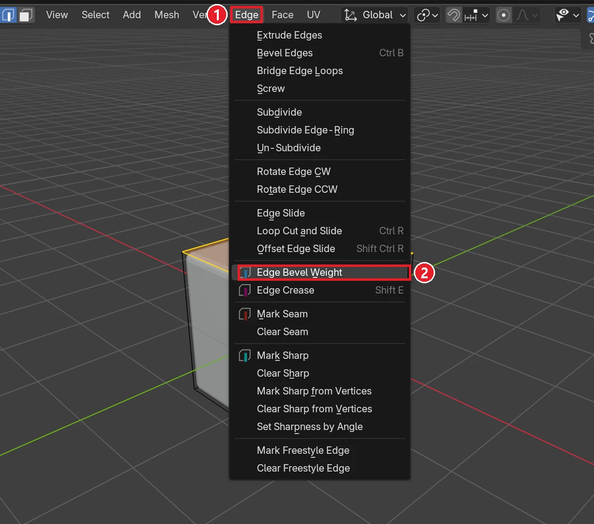 Figure 5. ① The Edge menu in the header ② Edge Bevel Weight. Edge Crease right below it is used in the subdivision post (Blender screenshot)
- Without moving the mouse, type
1and pressEnter. The 4 selected edges get a weight of 1. Typing a number adds it to the current value (0 at first). - Press
Tabto go back to Object Mode. - In the Bevel panel, set Limit Method to Weight and Amount to
0.2.
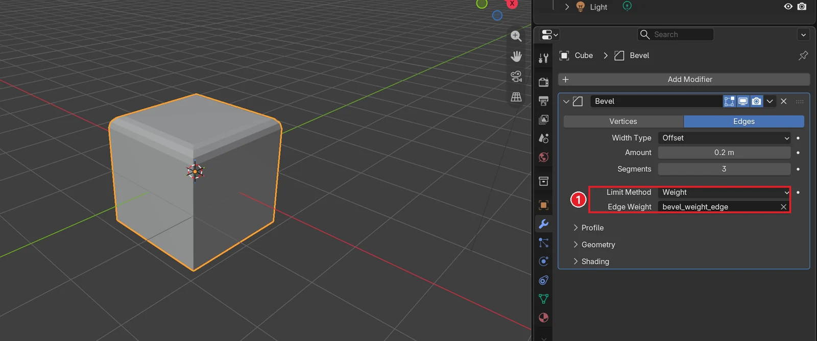 Figure 6. ① Limit Method Weight. bevel_weight_edge in the Edge Weight field is where the weights from step 4 are stored. Only the weighted top rim is cut (Blender screenshot)
Weights go from 0 to 1. Edges at 0 are not cut, and edges closer to 1 get the full Amount. An edge at 0.5 is cut about halfway. You can also see and change the values in Edit Mode with N (sidebar) → Item tab. This is handy later too: to bevel another edge, just select it in Edit Mode and give it a weight.
The last option, Vertex Group, bevels only edges between points in a vertex group (a named set of points). Use it on models that already use vertex groups.
4. When the cut is too wide: Clamp Overlap
With a very large Amount, the cuts of neighboring edges overlap. On a 2 m cube, cutting 1.5 m from every edge makes the cuts cross each other. With Clamp Overlap on, Blender stops the width just before they overlap.
Starting point: The default cube in a new file (File ‣ New ‣ General). Open the Modifiers tab again and add Bevel.
Follow along:
- Set Amount to
1.5and Segments to3. - Click the Geometry row at the bottom of the panel to expand it.
- Turn Clamp Overlap off.
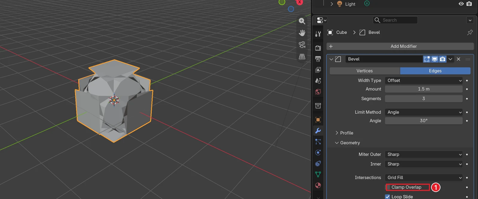 Figure 7. ① Clamp Overlap off: the bevel faces pass through each other and the shape tangles (Blender screenshot)
- Turn Clamp Overlap back on.
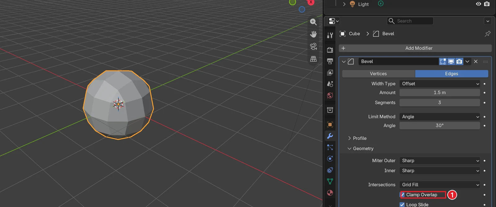 Figure 8. ① Clamp Overlap on (default): with the same 1.5 m Amount, the width stops just before overlapping and the shape stays clean (Blender screenshot)
Clamp Overlap is on by default. So if raising Amount stops changing the shape at some point, nothing is broken; this option has capped the width.
5. Also worth knowing: objects with unapplied scale
If you stretch an object in one direction with S in Object Mode (so its Scale is different per axis, like Scale X 2), Bevel stretches its width in that direction too and the edges are cut unevenly. With the mouse over the 3D Viewport, press Ctrl+A → Scale to apply the scale and the bevel evens out. A step-by-step version with pictures is in section 7 of Blender beginner chapter 7.
To see how this problem shows up when an AI builds a stack that includes Bevel, continue with Let AI build a modifier stack.
6. Practice
- On the cube from Figure 2, click Vertices. Compare what gets cut with Edges and write it down.
- On the cylinder (Figure 4), lower Angle to
10°. Check whether the side lines start to be cut. - On the cube from section 3-2, give one front vertical edge a weight of
0.5. See how its cut width differs from the top rim. - Expand the Profile row and change the Shape value. Find which way makes the cut concave and which makes it convex.
7. Common mistakes and fixes
| Symptom | Cause | Fix |
|---|---|---|
| Bevel doesn't cut the cylinder side | Limit Method Angle (30°) skips gentle edges | Normal. To cut the side too, lower Angle or use None |
| Edges are cut differently in each direction | The object's Scale differs per axis | Ctrl+A → Scale over the 3D Viewport (section 5) |
| Switching to Weight cuts nothing | No edge has a weight (all 0) | In Edit Mode select edges, Edge ‣ Edge Bevel Weight → 1 → Enter |
| Raising Amount stops changing the shape | Clamp Overlap caps the width | Normal. To cut further, turn Clamp Overlap off and check that faces don't tangle (section 4) |
| Bevel faces pass through each other | Clamp Overlap is off and Amount is large | Turn Clamp Overlap on, lower Amount |
| The cut looks faceted | Segments 1, or Shade Flat | Raise Segments; use Shade Smooth or Harden Normals |
| I can't find the Edge menu | You are in Object Mode | Press Tab to enter Edit Mode |
Summary in one line
Amount for width, Segments for roundness, Limit Method for where (Angle = sharp edges only, Weight = labeled edges only); Clamp Overlap stops a cut that is too wide. The next post covers the Subdivision Surface modifier, which smooths the whole shape.
Previous: Array modifier · Next: Subdivision Surface modifier · Whole series: Every Blender modifier in one list
References
- Blender 5.2 Manual: Bevel Modifier
- Blender 5.2 Manual: Edge Data (Edge Bevel Weight)
- Blender 5.2 Manual: Apply (Object Transformations)
- Shortcuts: Blender 5.2.1 default (Blender) keymap
- Image license: screenshots of Blender taken by AZTechnology. Blender license: blender.org/about/license