Boolean modifier: cutting holes, joining, intersecting, and fixing broken results
Use Blender's Boolean modifier to cut a round hole in a box, compare Difference, Union, and Intersect, and see on real screens how the result breaks when the cutter stays visible, has flipped faces, is an open mesh, or shares a face with the box, and how to fix each case.
한국어English
ON THIS PAGE
- 01Before you start
- 021. Add a cylinder as the cutter
- 032. Add the Boolean modifier and pick the cutter
- 043. Show the cutter as lines only
- 054. Compare the three operations
- 065. When the result breaks (1): the cutter's faces are flipped
- 076. When the result breaks (2): an open cutter and touching faces
- 087. Choosing a solver
- 09Practice
- 10Common mistakes and fixes
- 11Summary
- 12References
Based on: Blender 5.2 LTS (screenshots from 5.2.1, English interface, default shortcuts). Checked in November 2026. All images are real Blender screens. Red numbers, boxes, and the labels on comparison images were added for explanation. The Properties editor was widened so the text is easier to read.
If you want a round hole in a box, moving points one by one in Edit Mode takes a long time. With the Boolean modifier, you place a cylinder through the box and the hole appears. Move the cylinder and the hole follows. Turn the modifier off and the box is whole again.
A Boolean works like a cookie cutter. Press the cutter (the cylinder) into the dough (the box) and that shape is removed. Stick the cutter onto the dough and they join. Keep only the dough inside the cutter and you get the intersection. In this guide, the object that does the cutting is called the cutter. If modifiers are new to you, read What is a modifier? first. Other modifiers are in Every Blender modifier in one list.
When you finish this guide, you will be able to do the following.
- Cut a hole in a box with the Boolean modifier.
- Show the cutter as lines only, so you can see the result.
- Tell Difference, Union, and Intersect apart.
- Find the cause of a broken result: face direction, open mesh, or touching faces.
- Pick one of the three solvers (Float, Exact, Manifold) for the job.
Before you start
- Start from the default cube in a new file (File > New > General). Each side of the cube is 2 m.
- If Edit Mode and face selection are new to you, Blender beginner chapter 6: Edit Mode basics makes section 5 easier.
1. Add a cylinder as the cutter
Starting point: the default cube in a new file (File > New > General).
Follow along:
- With the mouse over the 3D Viewport, press
Shift+A> Mesh > Cylinder. - Open the Add Cylinder panel at the bottom left. Set Radius to
0.5 mand Depth to3 m.
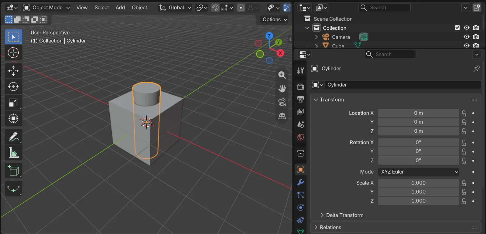 Figure 1. A cylinder passing straight through the middle of the box (Blender screenshot)
The cylinder (3 m) is taller than the box (2 m) on purpose. A cutter that sticks out well past the top and bottom gives a clean hole. Section 6 shows what happens when the heights are the same.
2. Add the Boolean modifier and pick the cutter
Starting point: the box and cylinder from the previous section.
Follow along:
- Click the box. The modifier goes on the object that gets the hole (the box).
- In the Properties editor, open the Modifiers tab (wrench icon) and choose Add Modifier > Generate > Boolean.
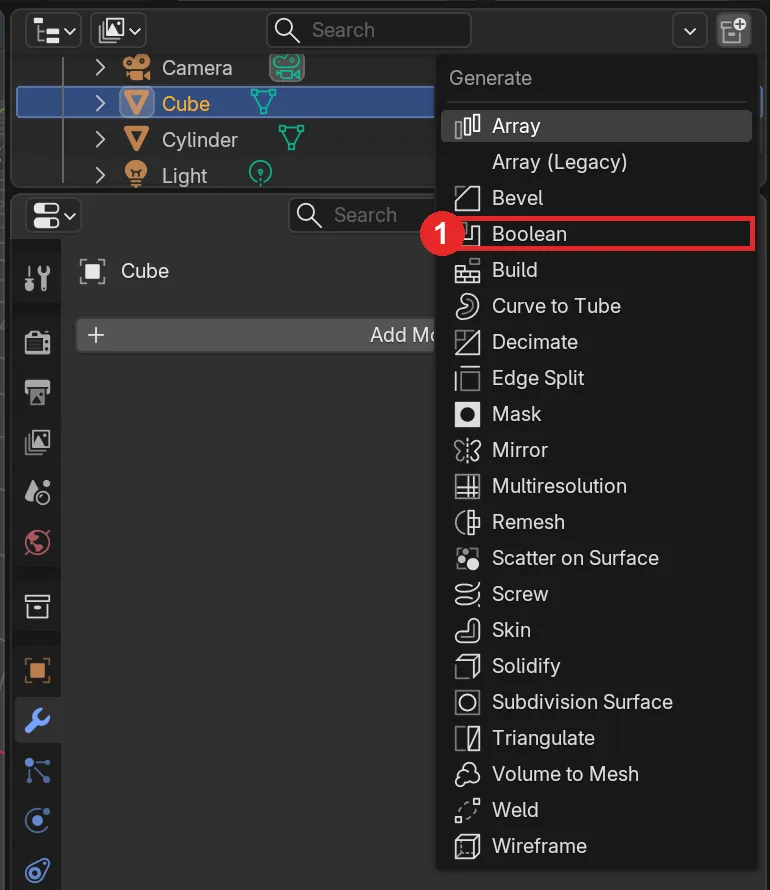 Figure 2. The Add Modifier > Generate menu. 1: Boolean (Blender screenshot)
- Click the Object field in the Boolean panel and choose
Cylinder. You can also use the eyedropper on the right of the field and click the cylinder in the viewport.
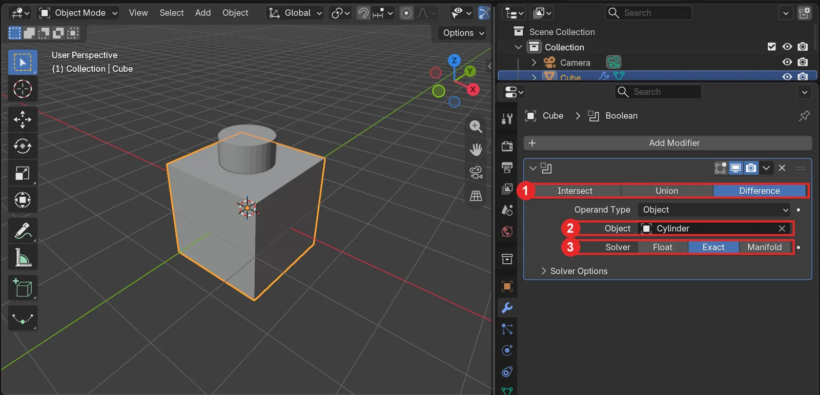 Figure 3. The Boolean panel. 1: operation (default Difference) 2: Object, the cutter cylinder 3: Solver (default Exact) (Blender screenshot)
The panel has three main parts.
| Field | Default | Meaning |
|---|---|---|
| Operation buttons | Difference | Remove the cutter (Difference), add it (Union), or keep only the overlap (Intersect) |
| Operand Type | Object | Use a single object as the cutter, or a whole collection |
| Solver | Exact | How the result is calculated. Section 7 compares all three |
But the viewport in Figure 3 looks the same as before. The hole is already there, but the cylinder fills it and is still drawn. This confuses almost everyone the first time.
3. Show the cutter as lines only
Starting point: the box with the Boolean from the previous section, and the cylinder.
The cutter is only used for the calculation. It should not be part of the result. So we show it as wire (lines only). You can still see where it is, which is handier than hiding it.
Follow along:
- Click the cylinder.
- In the Properties editor, open the Object tab (orange square icon) and expand the Viewport Display panel.
- Set Display As to
Wire.
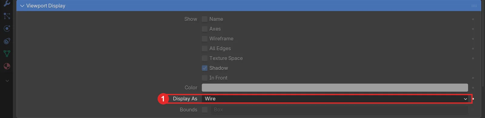 Figure 4. The cylinder's Object tab. 1: Display As: Wire. The image shows the Properties editor maximized (Blender screenshot)
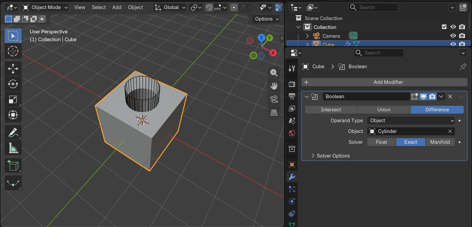 Figure 5. With the cylinder shown as lines, the hole in the box is visible (Blender screenshot)
Now move the cylinder with G. The hole follows it. The real box still has its 8 points. The hole is only a result the modifier draws on screen.
- To hide the cutter completely, select it and press
H, or turn off its eye icon in the Outliner. PressAlt+Hto show it again. - The cutter must not show up in renders either. An object set to Wire still renders normally, so also turn off its camera icon (render visibility) in the Outliner. If the Outliner has no camera icon, turn it on from the funnel (Filter) button at the top right of the Outliner.
4. Compare the three operations
Starting point: the box (Boolean) and the wire cylinder from the previous section.
Follow along: select the box and press the operation buttons at the top of the Boolean panel in this order: Difference, Union, Intersect.
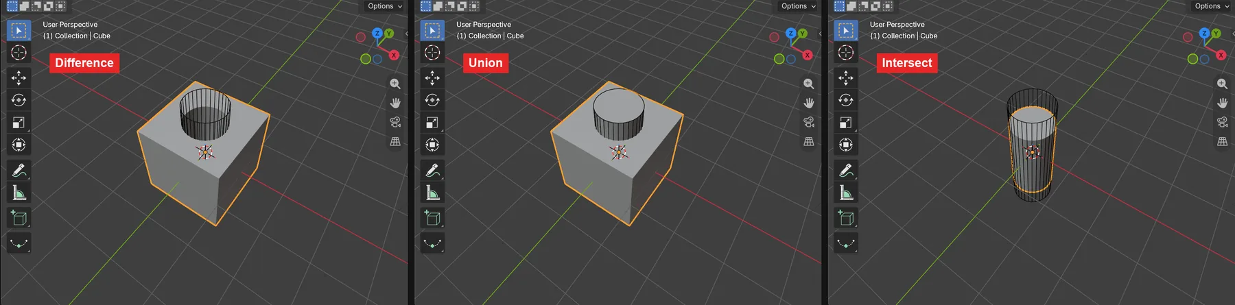 Figure 6. From left: Difference, Union, Intersect. The cylinder is still shown as lines (Blender screenshot)
| Operation | Result | Use it for |
|---|---|---|
| Difference | The cylinder's shape is removed from the box | Holes, grooves, window openings |
| Union | Box and cylinder become one piece, and faces buried inside are removed | Attaching handles or posts |
| Intersect | Only the overlapping part remains | Rounded blocks, lens shapes |
Union looks a lot like simply overlapping two objects. The difference is inside. Two overlapping objects keep faces that cut into each other. Union removes those inner faces and leaves one outer shell. This matters for 3D printing. For a full check, see Checking a model before 3D printing.
Before moving on, set the operation back to Difference.
5. When the result breaks (1): the cutter's faces are flipped
Starting point: the box (Boolean, Difference) and the cylinder from the previous section. In this section we break it on purpose and then fix it.
Each face of a mesh has a front and a back. The direction a face points to is called its normal. Like the skin of a balloon, all faces of a closed object should point outward. The cutter's inside and outside come from this face direction. If the cutter's faces are flipped, the result goes wrong.
Follow along (break it):
- Select the cylinder and press
Tabto enter Edit Mode. - Press
Ato select everything, choose Mesh > Normals > Flip, and pressTabto leave. - At the top right of the 3D Viewport, click the arrow next to Viewport Overlays (the two overlapping circles icon) and turn on Face Orientation.
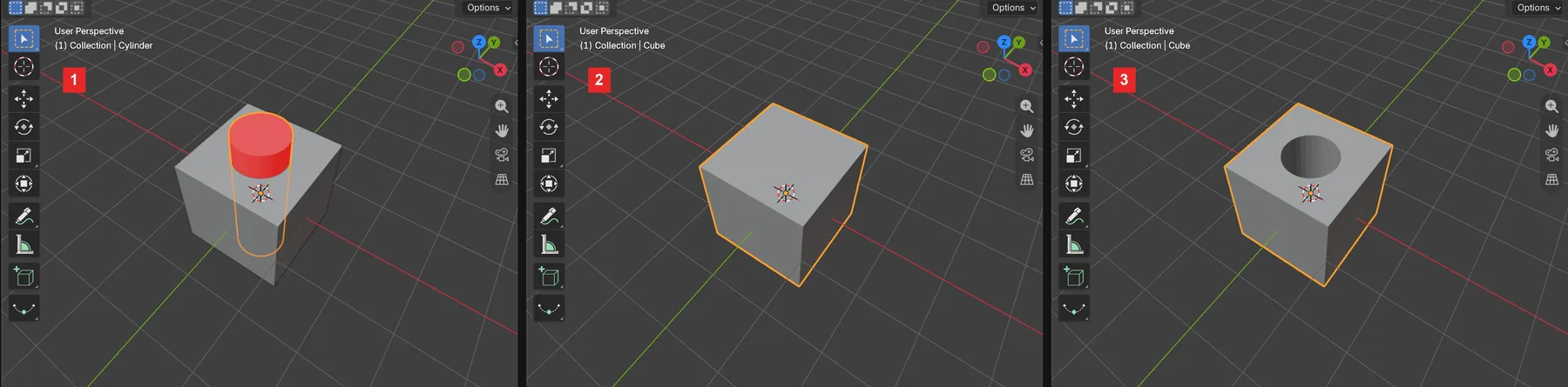 Figure 7. 1: the cylinder with flipped faces shows red 2: the hole in the box disappears 3: after Recalculate Outside the hole is back. Only panel 1 shows the cylinder with faces (Blender screenshot)
Face Orientation paints the back of faces red. The front color is transparent by default, so fronts stay gray. If the outside of the cutter is red, as in panel 1, its faces are flipped. Then, as in panel 2, the hole disappears and the box looks untouched.
Follow along (fix it):
- Select the cylinder and press
Tab, thenA. - Press
Shift+N(Mesh > Normals > Recalculate Outside) so all faces point outward. - Press
Tabto leave and turn Face Orientation off. If the cylinder's Display As is no longer Wire, set it to Wire again.
Flipped faces are common in models imported from other programs and in models built by hand, face by face. If a Boolean looks wrong, turn on Face Orientation first.
6. When the result breaks (2): an open cutter and touching faces
Starting point: the box and cylinder you fixed in the previous section. Select the cylinder, press X > Delete, and add a new one with the steps below.
6-1. A cylinder without caps and the Manifold solver
A manifold mesh is like a closed container that holds water without leaking. A mesh with holes, or with three or more faces on one edge, is non-manifold.
Follow along:
- Press
Shift+A> Mesh > Cylinder. In the Add Cylinder panel set Radius to0.5 m, Depth to3 m, and Cap Fill Type toNothing. You get a tube with no top or bottom. - Set the cylinder's Display As to
Wire(section 3). - Select the box and choose the new
Cylinderin the Boolean Object field. The field that pointed to the deleted cylinder is now empty. - Change Solver to Manifold.
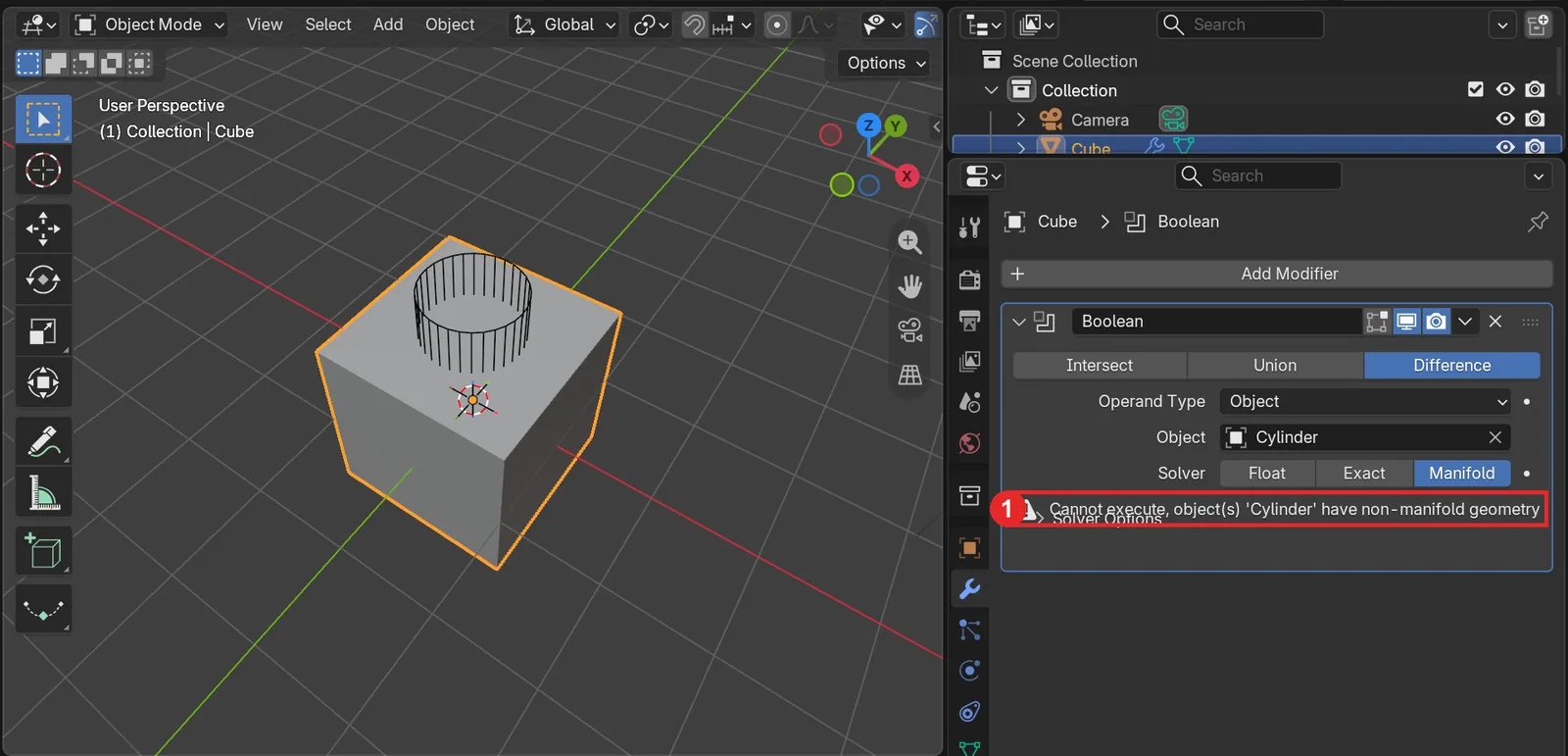 Figure 8. The Manifold solver with an uncapped cylinder. 1: a warning that it cannot calculate non-manifold geometry (Blender screenshot)
A warning appears and no hole is cut. The Manifold solver does not calculate non-manifold meshes at all. The only exception is a Difference with a single plane. Switch Solver to Exact and the same cylinder cuts a hole. Still, a mesh with holes can sometimes leave stray faces or marks even with Exact, and only closed meshes are sure to give a correct result. If the result looks wrong, open Solver Options and turn on Hole Tolerant, or cap the cutter so it is a closed object. Hole Tolerant is slower, so turn it on only when there is a problem.
6-2. A cylinder whose faces touch the box, and the Float solver
Follow along:
- Delete the cylinder and press
Shift+A> Mesh > Cylinder again. This time set Radius to0.5 mand Depth to2 m(the same height as the box). Leave Cap Fill Type at the defaultN-Gon. - Set the cylinder's Display As to
Wire, and choose the new cylinder in the box's Boolean Object field. - Change Solver to Float, hide the cylinder with
H, and look at the box. Then change Solver to Exact.
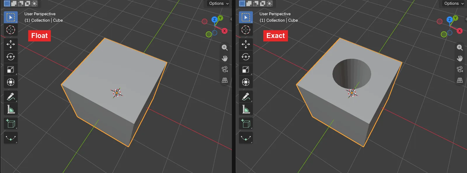 Figure 9. When the top of the cylinder and the top of the box are at the same height. Left Float, right Exact. The cylinder is hidden (Blender screenshot)
When the cutter's top face and the box's top face lie at the same height, Float closes the top, as on the left of Figure 9. Float is fast because it is a simple method that cannot handle overlapping faces. There are two fixes.
- Make the cutter a little longer so it sticks out at the top and bottom. This is why we used a depth of 3 m in section 1.
- Keep the solver on Exact. If you must use Float, raise Overlap Threshold in Solver Options a little.
7. Choosing a solver
| Solver | Speed | Good at | Weak at |
|---|---|---|---|
| Float | Fast | Simple shapes, cutters that stick out well | Touching or overlapping faces. Intersect cannot be used with a Collection cutter |
| Exact (default) | Slow | Overlapping faces, complex shapes. Most accurate | Cutters with flipped faces, very heavy models |
| Manifold | Usually the fastest | Closed (manifold) meshes | Does not calculate non-manifold meshes |
Start with the default, Exact. Try another solver only when the scene gets heavy and the viewport slows down. If you switch to Manifold and see a warning, first check that the cutter is closed, as in section 6-1.
Cutting many holes: adding one Boolean per cutter makes a long list of modifiers. Put all cutters in one collection and set Operand Type to Collection. Then one Boolean removes them all at once.
Making it permanent: to turn the result into real points, edges, and faces, click the down arrow at the top right of the Boolean panel > Apply. After applying, you can delete the cutter. Apply is hard to undo, so do it only when the shape is final.
Practice
- Add another cylinder, lay it down with
R>X>90, and add a second Boolean to the box to cut a sideways hole. Check that two Boolean panels are now stacked in the Modifiers tab. - Replace the cutter with
Shift+A> Mesh > UV Sphere and set the operation to Intersect. See what shape remains. - Put two cylinders in one collection, set Operand Type to Collection, and cut two holes with one Boolean.
Common mistakes and fixes
| Symptom | Cause | Fix |
|---|---|---|
| Nothing changes after adding Boolean | The cutter is shown and fills the hole | Set the cutter's Display As to Wire, or hide it with H (section 3) |
| The cutter shows up in renders | Wire display only affects the viewport | Turn off the cutter's render (camera) icon in the Outliner |
| The modifier is on the wrong object | Boolean was added to the cutter | Add it to the object that gets the hole, and pick the cutter in Object |
| The hole disappears and the box looks whole | The cutter's faces are flipped | Check for red faces with Face Orientation, then Shift+N (section 5) |
| A "non-manifold geometry" warning appears | Manifold solver with an open mesh | Switch to Exact, or close the cutter (section 6-1) |
| The top of the hole is closed | The cutter's face is at the same height (Float) | Make the cutter longer, or use Exact (section 6-2) |
| The viewport suddenly slows down | Exact is heavy to calculate | While working, turn off the modifier's monitor icon for a while, and turn it back on at the end |
Summary
Put the Boolean on the object that gets the hole, show the cutter as Wire, make the cutter long enough, and when it breaks, check face direction, closed mesh, and solver in that order.
In the next guide, Solidify modifier, you give thin faces some thickness.
Previous: Subdivision Surface modifier · Next: Solidify modifier · Whole series: Every Blender modifier in one list
References
- Blender 5.2 Manual: Boolean Modifier
- Blender 5.2 Manual: Object Viewport Display
- Blender 5.2 Manual: Viewport Overlays (Face Orientation)
- Read next: What is a modifier?, Blender beginner chapter 7: Modifiers, Checking a model before 3D printing
- Shortcuts: Blender 5.2.1 default (Blender) keymap
- Image license: screenshots of Blender taken by AZTechnology. Blender license: blender.org/about/license