Checking a model before 3D printing: find and fix holes, flipped faces and overlaps with built-in Blender tools
Use one deliberately broken cup to find holes, flipped faces and overlapping parts with Face Orientation, Non Manifold selection and the Intersect check in Mesh Analysis, then fix them with Recalculate Outside, Fill Holes and Boolean, and run a final check.
한국어English
ON THIS PAGE
- 01Before you start: make the example cup
- 021. What a printable model needs
- 032. See flipped faces with Face Orientation
- 043. Find holes and odd edges with Non Manifold
- 054. Fix face directions with Recalculate Outside
- 065. Fill the hole
- 076. Find overlaps with Mesh Analysis
- 087. Join the handle with Boolean
- 098. Final check
- 10Practice
- 11Common mistakes and fixes
- 12Summary
- 13References
Based on: Blender 5.2 LTS (screenshots from 5.2.1, English interface, default shortcuts). Checked in November 2026. All pictures are real Blender screenshots. The red numbers and boxes were added to explain them. Some pictures have the scene Statistics overlay turned on.
A model can look fine in Blender and still go wrong in a 3D printer program (a slicer). Walls come out empty, odd spots get filled, or the slicer shows an error. The cause is often one of three things that are hard to see: holes, flipped faces and parts that cut into each other.
In this guide you check one cup that has all three problems on purpose. You only use tools that come with Blender. Setting the size, checking wall thickness and sending the file to a slicer are covered in From Blender to a 3D printer. This guide is the step before that: "can this model hold water?"
By the end of this guide you will be able to:
- Look for flipped faces with Face Orientation.
- Find holes and odd edges with Non Manifold selection.
- Fix face directions and holes with Recalculate Outside and Fill Holes.
- Find overlapping parts with the Intersect check in Mesh Analysis and join them with Boolean.
- Confirm at the end that Non Manifold selects nothing.
Before you start: make the example cup
To follow along with the same cup as the pictures, make it in this order. To check your own model right away, skip this section and go to section 1. If lengths are not shown in mm, set Length to Millimeters in the Scene tab > Units of the Properties editor.
- In a new file (File > New > General), delete the default cube with
X> Delete. - Add
Shift+A> Mesh > Cylinder, and in the Add Cylinder panel at the bottom left set Vertices32, Radius30 mm, Depth80 mm, Location Z40 mm. Rename itCup. - Press
Tabfor Edit Mode, press3for face select, click the top face and delete it withX> Faces. That is the cup opening. - Hover over the side and press
Ctrl+R, click, then right-click to leave the cut in the middle. In the Loop Cut and Slide panel at the bottom left, set Number of Cuts to7. The side is now split into 8 rows, each 10 mm tall. - Press
Tabto go back to Object Mode, add Add Modifier > Generate > Solidify in the Modifier tab, and set Thickness to2.5 mm. Be sure to apply it with the arrow next to Solidify > Apply. If you delete faces without applying, the modifier closes the hole edge again and you will not get the result in the pictures. - Press
Tab→3→ numpad1(front view). On the outer wall,Shift+click a 2x2 block of faces (4 faces) in the third and fourth rows from the bottom, a little left of center, and delete them withX> Faces. That is the hole. - A little further to the right, select a 2x2 block of faces in the sixth and seventh rows from the bottom and click Mesh > Normals > Flip. Those are the flipped faces.
- Press
Alt+A, then, still in Edit Mode, addShift+A> Torus. Adding it in Edit Mode makes it part of the same object as the cup. In the Add Torus panel set Major Segments24, Major Radius18 mm, Minor Radius5 mm, Location X28.5 mm, Location Z45 mm, Rotation X90°. - Keep only the right half of the ring. With only the new ring selected, choose Mesh > Bisect and draw one vertical line anywhere on the screen. In the Bisect panel at the bottom left set Plane Point X
28.5 mm, Plane Normal X1, Y0, Z0, and turn on Fill and Clear Inner. The left half is removed and the cut ends get cap faces, so you get a half handle that cuts about 1.5 mm into the cup wall. - Press
Alt+AandTabto go back to Object Mode.
1. What a printable model needs
A slicer treats the model as a container with a clear inside and outside. Only then can it decide "plastic goes up to here" and cut the layers. This state is called manifold, often "watertight". Think of a cup that does not leak when you pour water in.
| Problem | What it is | What happens in the slicer |
|---|---|---|
| Hole | A missing face connects inside and outside | It does not know how far to fill, so walls come out empty or filled wrongly |
| Flipped face | The front and back of a face are swapped | It reads that spot as inside and treats it like a hole |
| Overlap | Two pieces cut into each other | The hidden inner walls stay and the result is messy or fails |
Every face has a front and a back. The front must face outward so Blender and the slicer know "this side is outside". The direction the front faces is the normal. Think of the printed side of a sheet of paper as its front.
2. See flipped faces with Face Orientation
Start state: Start from the cup made in "Before you start". To check your own model, start with that model selected.
Steps:
- Click the arrow next to the Viewport Overlays button (two overlapping circles) at the top right of the 3D Viewport.
- Turn on Face Orientation in the list.
- Turn the model around and look for red areas.
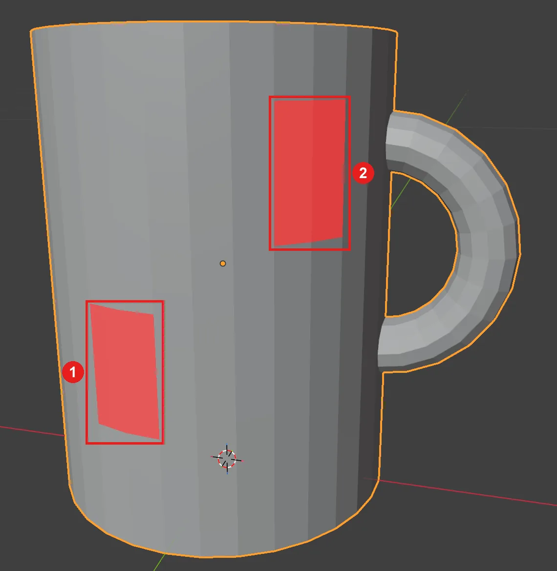 Figure 1. The cup with Face Orientation on. ① The back of the inner wall seen through a hole ② Four flipped faces (Blender screenshot)
With the default colors, front faces have no color and only back faces are red. If you see red from outside, a back face is facing outward there.
Figure 1 has two red areas. ② is where faces are really flipped. ① is not a flipped face but a hole. The outer wall is missing, so you see the back of the inner wall behind it. Face Orientation alone cannot easily tell the two apart. The Non Manifold selection in the next section does.
3. Find holes and odd edges with Non Manifold
Non Manifold selects every place that "breaks the container rules" at once. With default settings it selects all of these:
- Edges used by only one face. Hole borders are in this group.
- Edges shared by three or more faces.
- Places where neighboring faces point in opposite directions.
- Points that are not attached to any face or edge.
Start state: Continue from the cup in the previous section.
Steps:
- Press
Tabfor Edit Mode and1for vertex select mode. In face select mode, Non Manifold does not appear in the menu. - Press
Alt+Ato deselect everything. - Choose Select > Select All by Trait > Non Manifold. It has no default shortcut.
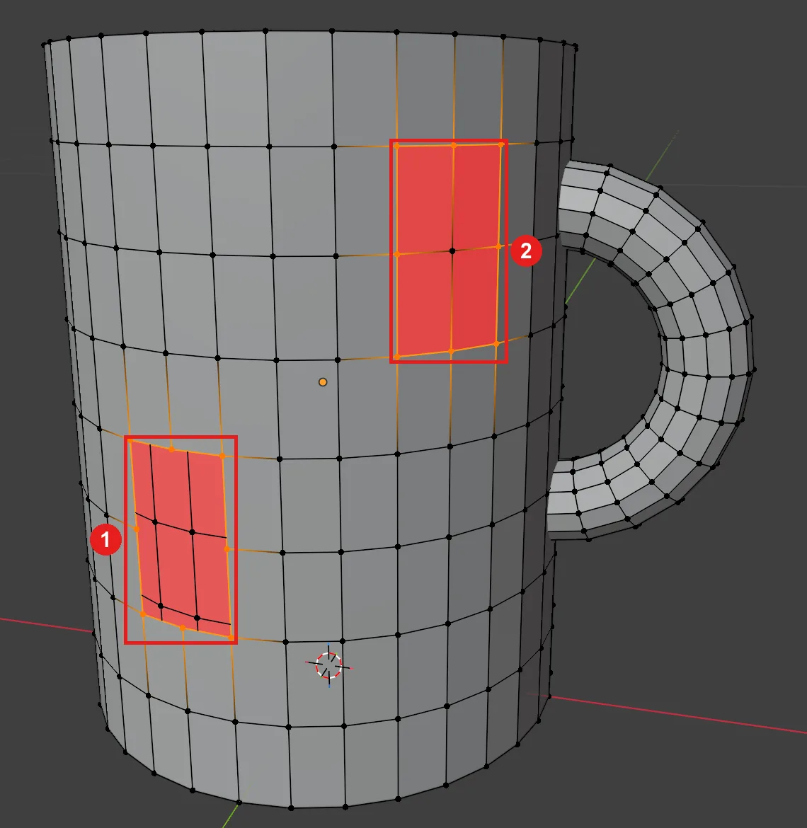 Figure 2. What Non Manifold selected. ① Border of the hole ② Border of the flipped faces (Blender screenshot)
On the example cup, 16 points were selected: the hole border and the border of the flipped faces. Turn on Statistics in the Viewport Overlays list to see "selected / total" at the top left.
4. Fix face directions with Recalculate Outside
Start state: Continue in Edit Mode from the previous section.
Steps:
- Press
Ato select everything. - Choose Mesh > Normals > Recalculate Outside. The shortcut is
Shift+N. Blender turns every face so its front faces outward. - Press
Alt+A, then select Non Manifold again as in section 3.
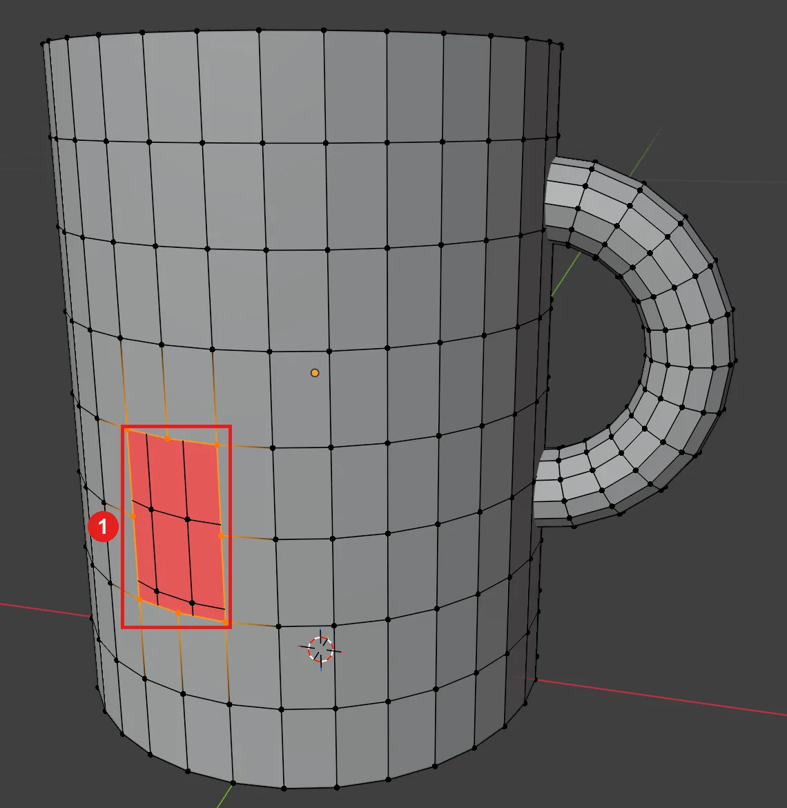 Figure 3. After Recalculate Outside. The flipped faces are gone and ① only the hole is left (Blender screenshot)
The flipped faces are grey again. This time only the 8 points around the hole were selected.
5. Fill the hole
Start state: Continue in Edit Mode from the previous section.
Steps:
- Press
Ato select everything. - Choose Mesh > Clean Up > Delete Loose. Any loose points and edges not attached to faces are deleted. The example cup has none, but on other models it is good to tidy them before filling holes.
- Press
Aagain and choose Mesh > Clean Up > Fill Holes. - Open the Fill Holes panel at the bottom left and set Sides to
0. Sides means "only fill holes with this many sides or fewer". The default 4 fills square holes only. The example hole has 8 sides, so the default does nothing. 0 fills all holes no matter their size. - Press
Shift+Nonce more so the new face points the right way. - Press
Alt+Aand select Non Manifold again.
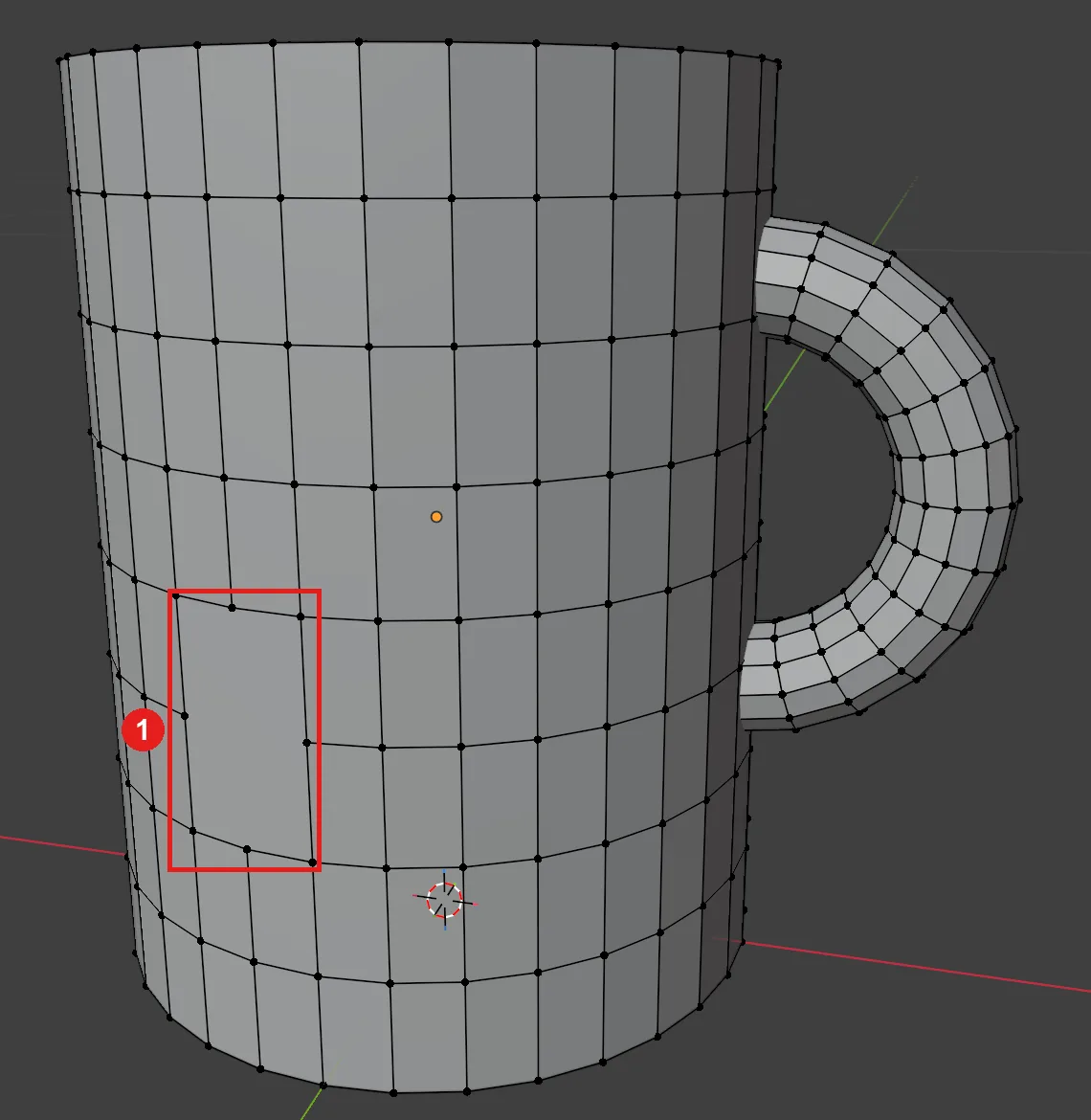 Figure 4. After filling the hole. ① The spot filled with one 8-sided face (Blender screenshot)
Now nothing is selected. The hole and the flipped faces are gone. Filling a large hole with one face makes that spot flat. If the spot must stay curved, select the border points, make a face with F, and split it with the Knife tool (K) by hand.
6. Find overlaps with Mesh Analysis
Even with no holes and correct normals, one problem can remain. The handle of the example cup cuts into the cup wall. The handle and the cup are each closed containers, so Non Manifold does not catch this.
Start state: Continue in Edit Mode from the previous section.
Steps:
- In Edit Mode, click the arrow next to the Mesh Edit Mode overlay button at the top right of the 3D Viewport (to the right of Viewport Overlays, shown only in Edit Mode).
- Turn on Mesh Analysis near the bottom of the list and set Type to Intersect.
- Look for red areas.
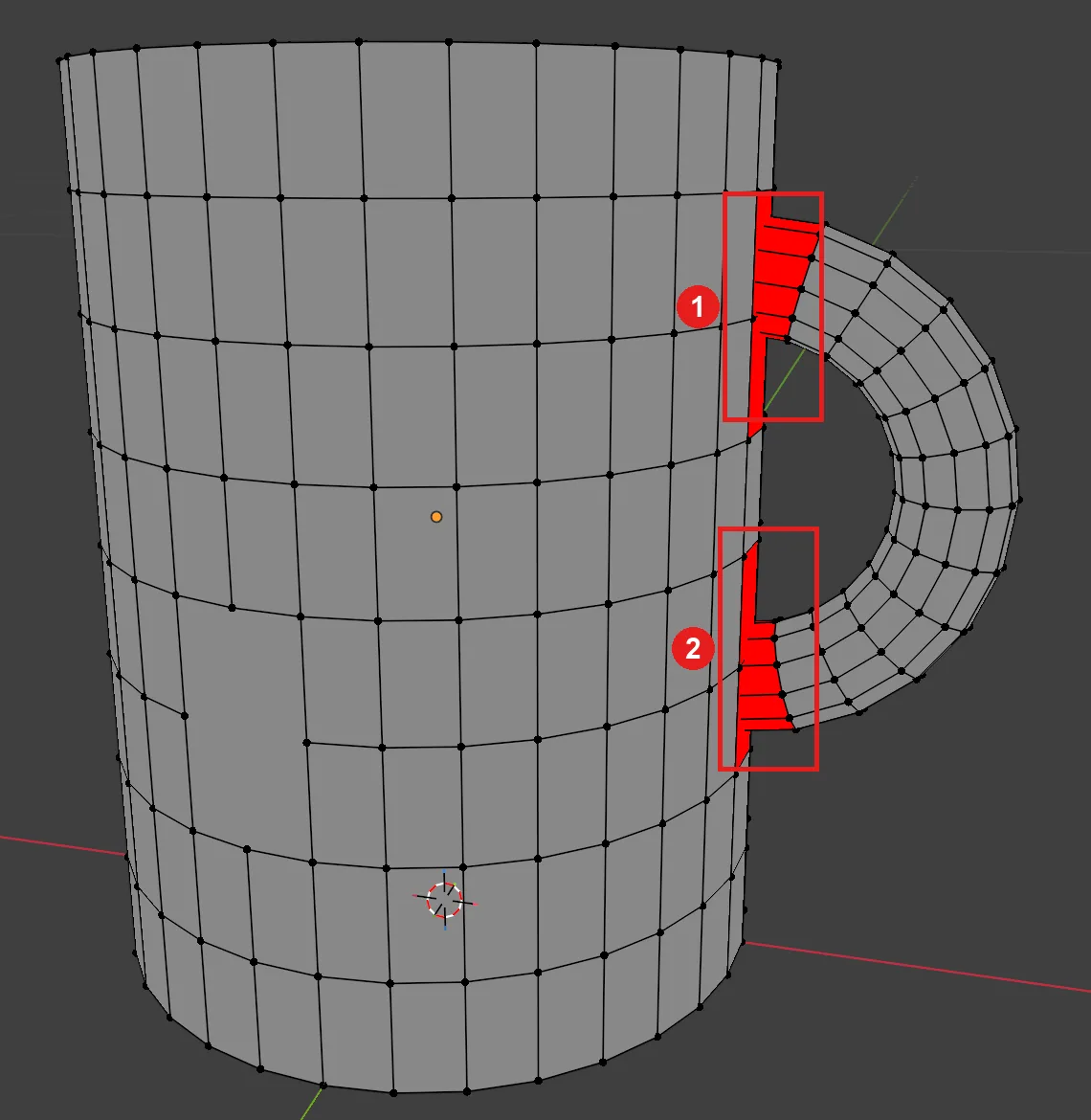 Figure 5. Intersect check. ① Where the top of the handle cuts into the wall ② The bottom spot (Blender screenshot)
Intersect paints faces that cut into each other red. Set Type to Thickness to see thin walls. The thickness check is covered step by step in section 3 of From Blender to a 3D printer. Mesh Analysis colors do not show with X-ray on, so look in Solid view with X-ray off.
7. Join the handle with Boolean
To join two overlapping pieces into one, use the Union mode of the Boolean modifier. It is like pressing two lumps of clay together into one.
Start state: Continue in Edit Mode from the previous section.
Steps:
- Hover the mouse over the handle and press
Lto select only the handle. If part of the cup is selected too, pressAlt+A, click one point of the handle and pressCtrl+L. - Choose
P> Selection. The handle becomes a separate object. - Press
Tabto go back to Object Mode. Rename the new objectHandlein the Outliner. - Select the cup and add Add Modifier > Generate > Boolean in the Modifier tab.
- Click Union (② in Figure 6) and pick
Handlein the Object field (③ in Figure 6). - Click the eye icon of Handle in the Outliner to hide it (① in Figure 6).
- Click the arrow next to the Boolean name > Apply.
- Press
Tabfor Edit Mode, select everything withA, then pressM> By Distance (Merge by Distance). - Choose Mesh > Clean Up > Degenerate Dissolve. Press
Tabto go back to Object Mode. - Turn the eye icon of Handle back on in the Outliner, select Handle and delete it with
X> Delete. Its shape is already part of the cup, so you no longer need it. If you leave it, it may end up in the STL export too.
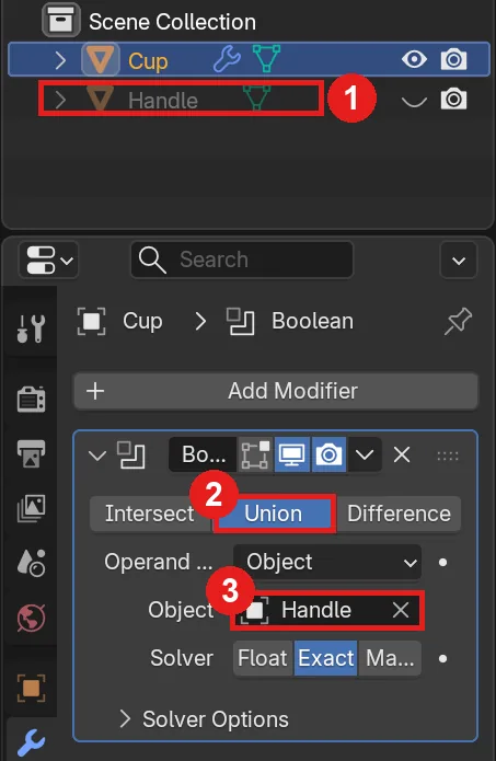 Figure 6. Boolean settings. ① Hidden Handle ② Union ③ Handle in the Object field (Blender screenshot)
Steps 8 and 9 tidy the joint. A Boolean join can leave points at almost the same position or very thin faces where the pieces meet. In the example, Merge by Distance took the point count from 737 to 733, down by 4.
8. Final check
Start state: Continue from the joined cup in the previous section.
Steps:
- In Edit Mode, press
1(vertex select) →Alt+A→ Select > Select All by Trait > Non Manifold. - Turn on Statistics in Viewport Overlays and read the numbers at the top left.
- Check once more that the Intersect check in Mesh Analysis shows no red.
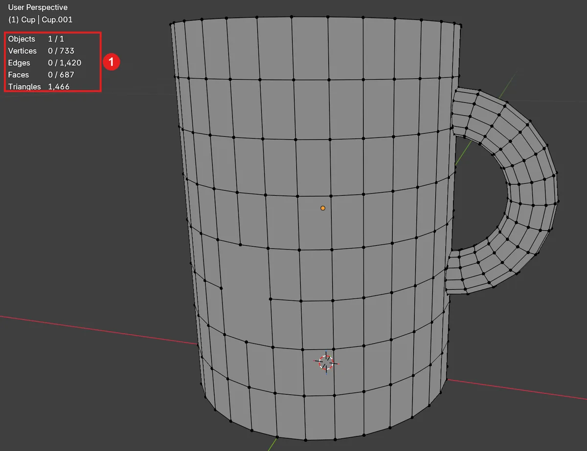 Figure 7. Final check. ① Selected points, edges and faces are all 0 (Blender screenshot)
If the first number is 0, as in Vertices 0 / 733, the hole and flipped-face checks pass. Last, look down into the cup to make sure no part of the handle sticks out on the inside (Figure 8).
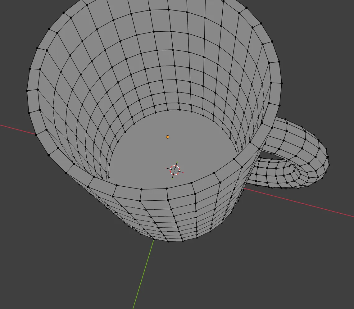 Figure 8. Inside the cup from above. The handle is attached only to the outer wall (Blender screenshot)
When all three checks pass, export STL and load it into a slicer. Check wall thickness separately with the thickness check in From Blender to a 3D printer.
If you check models often, the 3D Print Toolbox extension is also useful. It is an official extension that puts volume and surface area, a check for bad geometry with a Make Manifold fix, and STL, PLY and OBJ export in one panel, and it works with Blender 4.2 LTS and newer. Learning the built-in checks in this guide first makes it easier to understand what the tool does.
Practice
- Add a cube, delete one face in Edit Mode, and write down how many points Non Manifold selects.
- On the same cube, leave Fill Holes Sides at 4 and check that it fills. Then make a 6-sided hole and try again.
- Place two cylinders in a cross, Join them (
Ctrl+J), and find the overlap with the Intersect check. - Join the cylinders from step 3 with Boolean Union, confirm Non Manifold selects 0, and save the file.
Common mistakes and fixes
| Symptom | Cause | Fix |
|---|---|---|
| Non Manifold is missing from Select All by Trait | Face select mode | Switch to vertex or edge mode with 1 or 2 |
| Fill Holes did nothing | Sides defaults to 4, so larger holes are skipped | Set Sides to 0 in the Fill Holes panel |
| No blue in Face Orientation | Front faces are transparent by default | Just look for red |
| A fixed red area is red again | It is the back of the inner wall behind a hole | Check with Non Manifold whether it is a hole first |
| Mesh Analysis is not in the list | Object Mode | Enter Edit Mode with Tab and open the Mesh Edit Mode overlay |
| The Boolean result looks wrong | One of the objects has holes | Get both objects to 0 Non Manifold first, then use Boolean |
Summary
Look for red with Face Orientation, find holes with Non Manifold, fix with Shift+N, Fill Holes (Sides 0) and Boolean Union, and finish when the selected count is 0.
References
- Blender 5.2 manual, Select All by Trait (Non Manifold): https://docs.blender.org/manual/en/5.2/modeling/meshes/selecting/all_by_trait.html
- Blender 5.2 manual, overlays (Mesh Analysis): https://docs.blender.org/manual/en/5.2/editors/3dview/display/overlays.html
- Blender 5.2 manual, Boolean modifier: https://docs.blender.org/manual/en/5.2/modeling/modifiers/generate/booleans.html
- Blender 5.2 manual, Clean Up (Delete Loose, Degenerate Dissolve, Fill Holes): https://docs.blender.org/manual/en/5.2/modeling/meshes/editing/mesh/cleanup.html
- Blender Extensions, 3D Print Toolbox: https://extensions.blender.org/add-ons/print3d-toolbox/
- Shortcuts: Edit Mode
Tab, vertex select1, select allA, deselectAlt+A, recalculate normalsShift+N, select linkedL/Ctrl+L, separateP, merge menuM - Pictures: all real Blender 5.2.1 screenshots. The cup is an example made for this guide