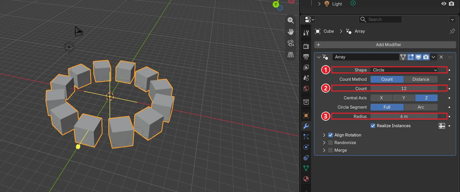
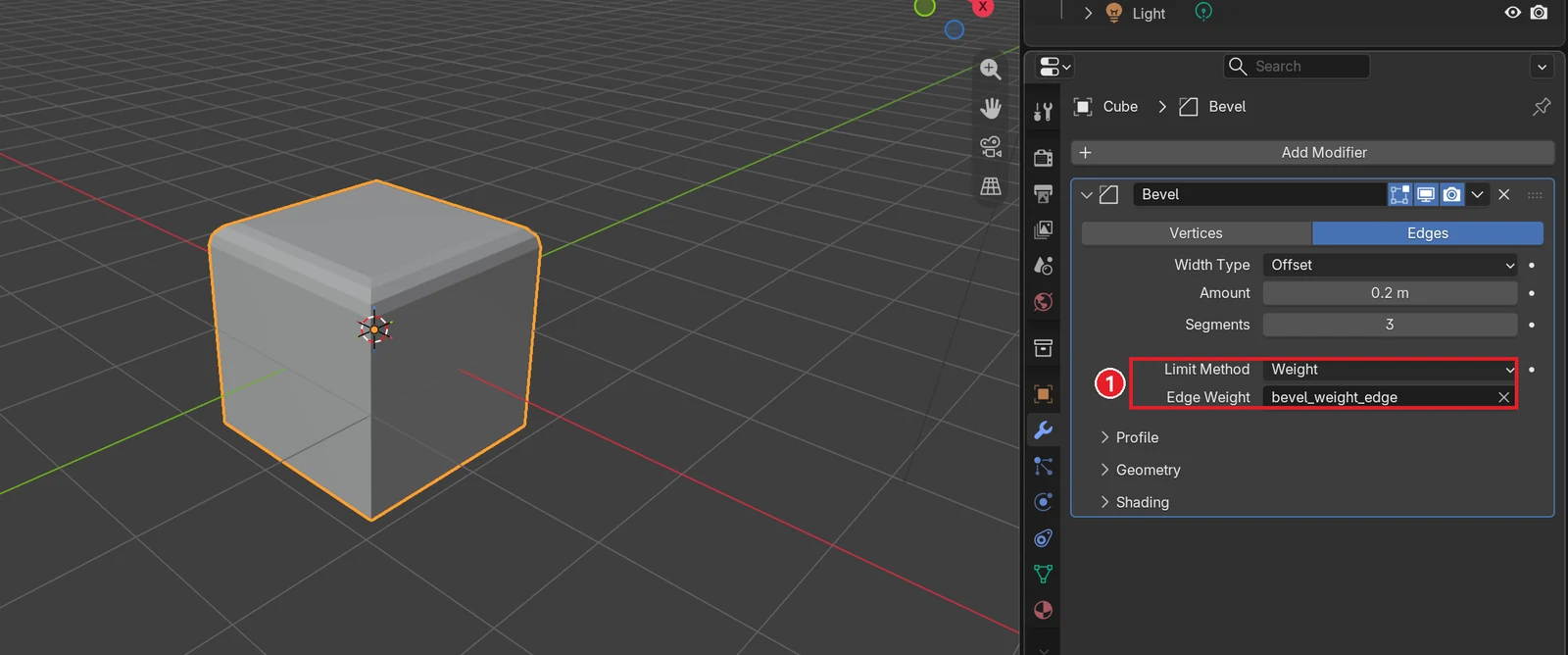
Displace and Shrinkwrap modifiers: bumpy ground from a texture, and sticking to another surface
Put a Displace modifier with a Clouds texture on a flat grid to make hilly ground, and see how Strength, Midlevel, and point count change the result. Then use the Shrinkwrap modifier to stick a road strip onto that ground, compare Nearest Surface Point with Project, and go through modifier order mistakes, all on real screens.
한국어English
ON THIS PAGE
- 011. Prepare a plane with many points
- 022. Add Displace: without a texture the whole panel floats
- 033. Make hills with a Clouds texture
- 044. Set the height and the detail
- 055. Modifier order mistakes
- 066. Stick a road strip to the ground with Shrinkwrap
- 077. Nearest Surface Point and Project
- 08Practice
- 09Common mistakes and fixes
- 10Summary
- 11References
Based on: Blender 5.2 LTS (screenshots from 5.2.1, English interface, default shortcuts). Checked in November 2026. All images are real Blender screens. Red numbers, boxes, and the labels on comparison images were added for explanation. The Properties editor was widened so the text is easier to read. From Figure 9 on, the road strip is colored blue so it stands out from the ground.
Shaping ground with hills by hand means raising and lowering thousands of points one by one. The Displace modifier reads a black-and-white pattern (a texture) and raises the bright parts and lowers the dark parts. It is like laying bumpy stones under a flat sheet: the sheet rises in the shape of the stones.
Once the ground is made, you need to put things on it, like a path, a puddle, or a patch of moss. The ground is bumpy, so a flat panel either floats or sinks into it somewhere. The Shrinkwrap modifier sticks a panel's points onto another object's surface. It works like plastic wrap over a bowl, which clings to the bowl's shape.
This is the last guide in the modifier series, so at the end it collects mistakes caused by modifier order in one place.
When you finish this guide, you will be able to do the following.
- Make hilly ground with Displace and a Clouds texture.
- Set the height with Strength and Midlevel, and the detail with point count.
- Stick a road strip onto the ground with Shrinkwrap.
- Choose between Nearest Surface Point and Project.
- Tell when modifier order changes the result.
1. Prepare a plane with many points
Starting point: a new file (File > New > General). Select the default cube and delete it with X > Delete.
Displace moves points up and down. A plane with only four points moves only its four corners, no matter what pattern you give it. So we start with a dense grid.
Follow along:
- With the mouse over the 3D Viewport, press
Shift+A> Mesh > Grid. - Open the Add Grid panel at the bottom left and enter X Subdivisions
100, Y Subdivisions100, and Size10 m.
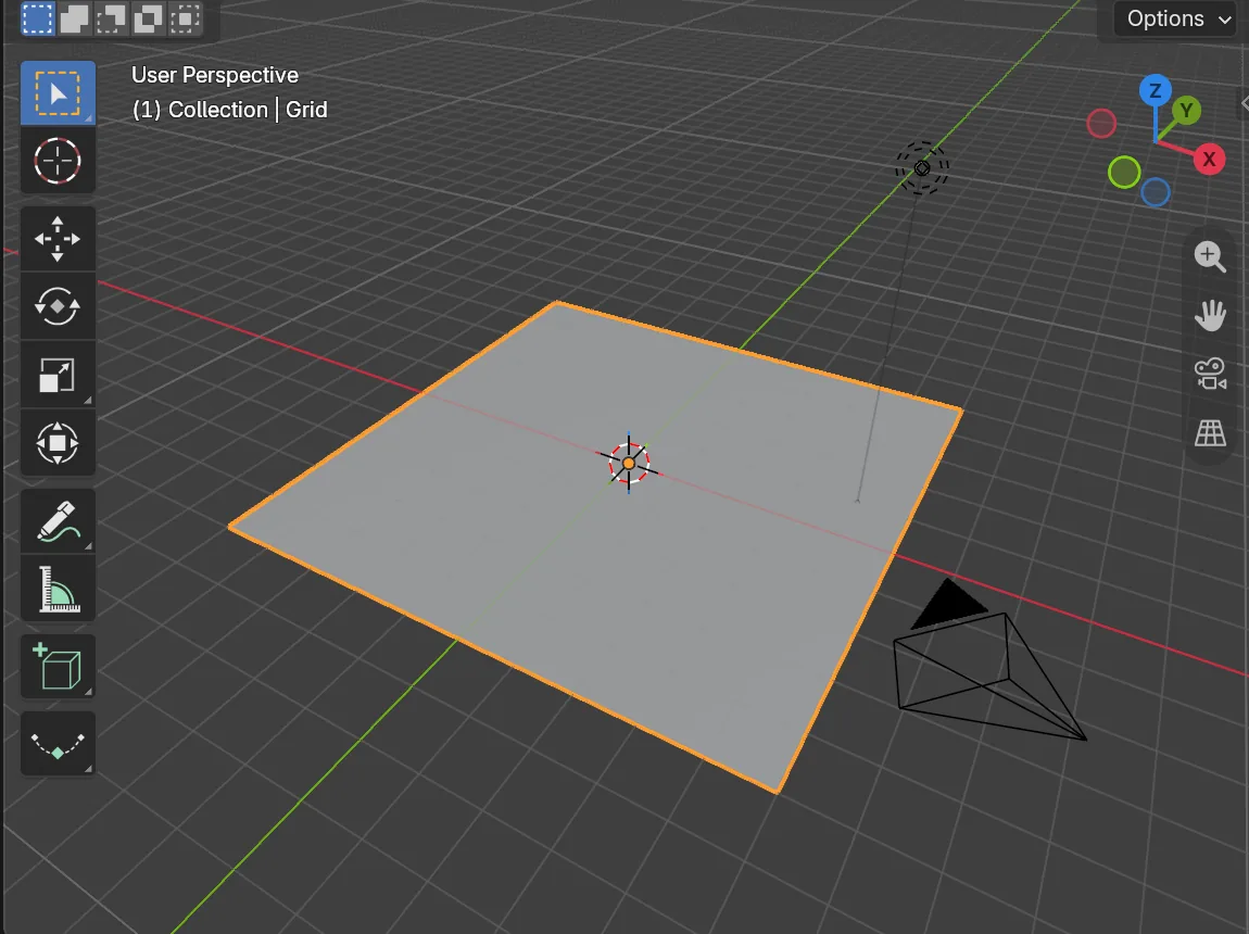 Figure 1. A grid 10 m on each side with 100 by 100 faces (Blender screenshot)
100 by 100 means 10,000 faces and a little over 10,200 points. That seems like a lot for one floor panel, but you need about this many to show the shape of the ground (section 4 compares).
2. Add Displace: without a texture the whole panel floats
Starting point: the grid from the previous section (named Grid), selected in Object Mode.
Follow along: in the Properties editor, open the Modifiers tab (wrench icon) and choose Add Modifier > Deform > Displace.
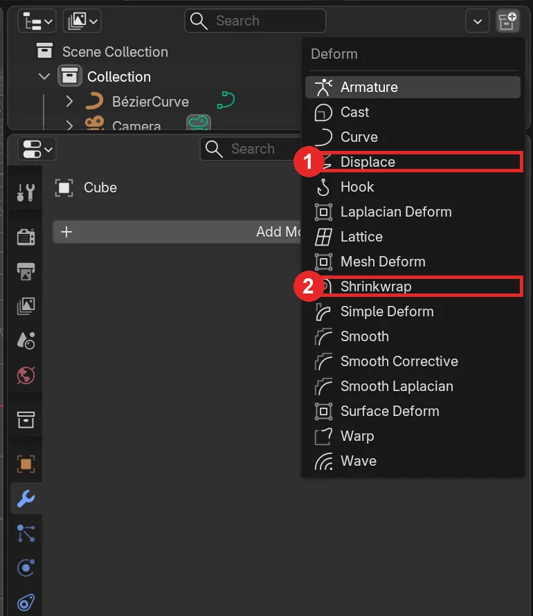 Figure 2. The Add Modifier > Deform menu. 1: Displace 2: Shrinkwrap (section 6) (Blender screenshot)
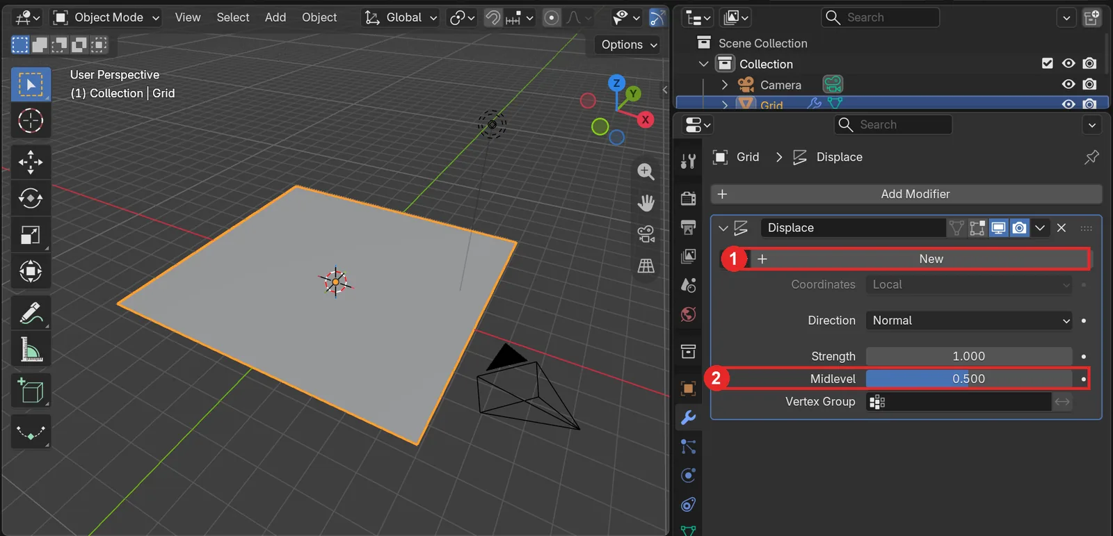 Figure 3. Displace added with no texture. 1: New in the texture field 2: Midlevel 0.5 (Blender screenshot)
The ground does not get bumpy. The whole panel rises 0.5 m and stays flat. When the texture field is empty, Displace reads every point as 1.0 (white). The distance a point moves is:
distance moved = (texture value − Midlevel) × Strength
Here that is (1.0 − 0.5) × 1 = 0.5 m. The direction (Direction) is Normal by default, which means the way the face points. On a flat plane that is up. If "the panel just floated up", you have not picked a texture yet.
3. Make hills with a Clouds texture
Starting point: the grid from the previous section (Displace, no texture).
Follow along:
- Click New in the texture field of the Displace panel. A texture named
Textureis created. Its first type is Image or Movie, so there is no pattern yet. - Click the Texture tab (checkerboard icon) at the bottom of the tab column on the left of the Properties editor.
- Change Type to
Clouds. The Preview shows a black-and-white cloud pattern. - In the Clouds panel below, change Size from the default
0.25to1.5.
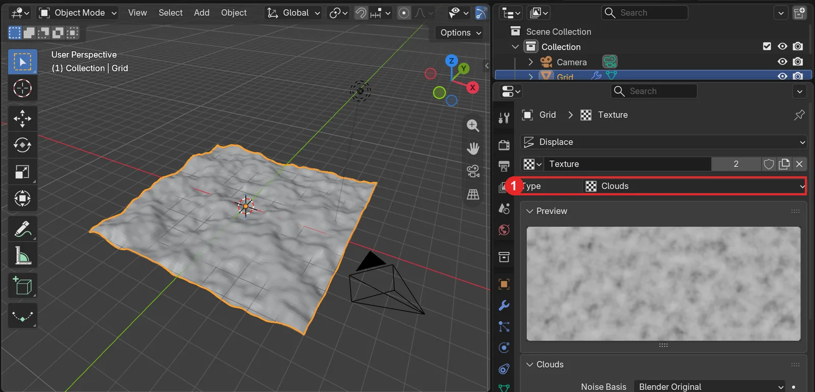 Figure 4. The Texture tab. 1: Type: Clouds. The image is after Size was changed to 1.5 (Blender screenshot)
- Go back to the Modifiers tab.
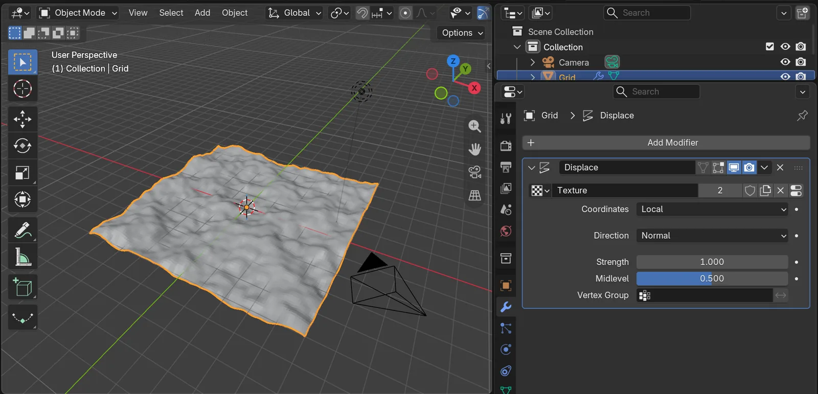 Figure 5. Ground made with a Clouds texture (Blender screenshot)
Size in Clouds is the size of one blob of the pattern. Small values give a rocky field, and large values give gentle hills. With the default 0.25, the bumps on this 10 m grid are too small and it looks like rough, rocky ground.
4. Set the height and the detail
4-1. Strength and Midlevel
Starting point: the ground from the previous section (Strength 1, Midlevel 0.5).
Follow along: change Strength to 2, then set it back to 1. Next change Midlevel to 0, then set it back to 0.5.
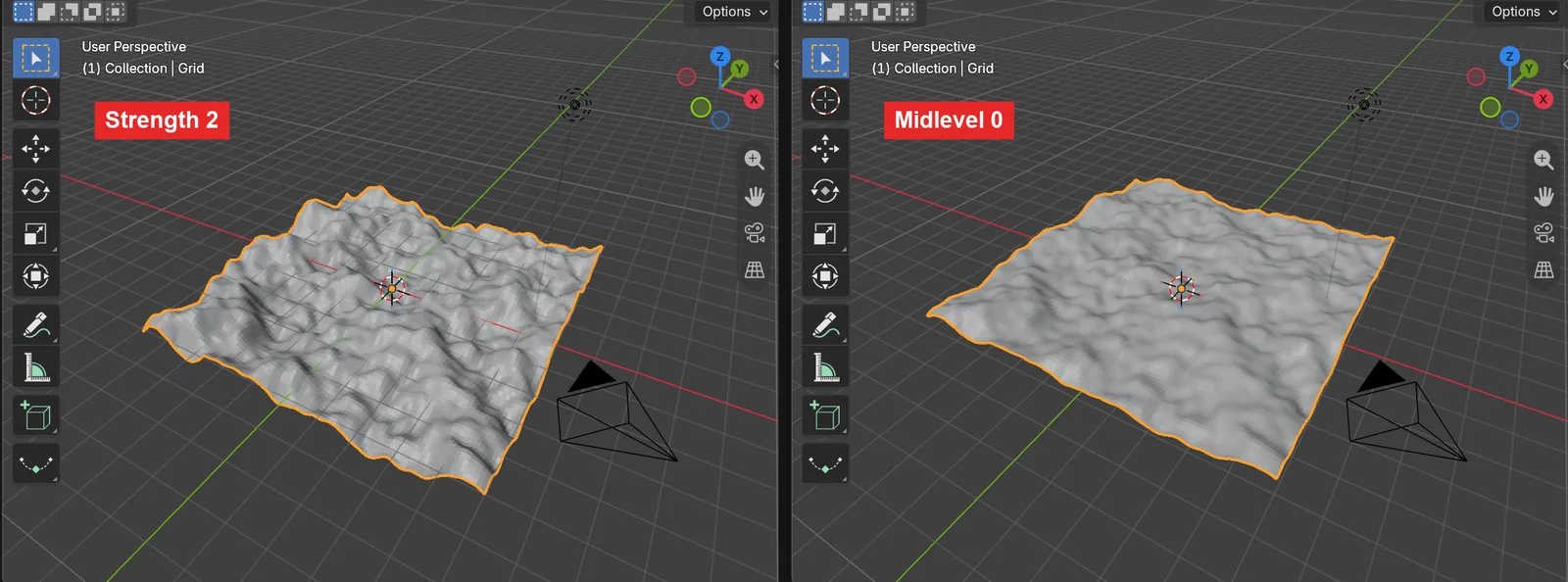 Figure 6. Left Strength 2, right Midlevel 0 (Blender screenshot)
| Field | What changing it does | Picture it as |
|---|---|---|
| Strength | Makes the height difference bigger or smaller. Negative values swap hills and valleys | How hard the stones push up |
| Midlevel | Moves the whole ground up or down. Brightness equal to this value stays in place | Where you set the floor level |
Midlevel 0.5 means "middle gray stays in place, brighter goes up, darker goes down". At 0, only black stays in place, so almost every point goes up. If the ground must sit at the level of a floor panel, it is easier to keep 0.5 and set the height with the object's position.
4-2. Point count
Starting point: select the grid from the previous section and hide it with H.
Follow along:
- Press
Shift+A> Mesh > Grid and set X and Y Subdivisions to10and Size to10 m. - Add Add Modifier > Deform > Displace, and choose the
Textureyou made earlier from the list next to the texture field.
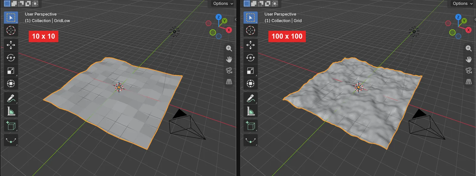 Figure 7. Same texture, same values. Left 10 by 10, right 100 by 100 (Blender screenshot)
Same texture, same Strength, but the results are completely different. No matter how fine the texture is, height only changes where there is a point to read it. It is like printing a newspaper photo with large dots: the face gets blurred. More points mean more detail, but also more weight.
5. Modifier order mistakes
Starting point: the 10 by 10 grid (Displace) from the previous section, still selected.
5-1. Subdivision Surface goes above Displace
If you lack points, you can add them with Subdivision Surface. But where you put it matters.
Follow along:
- Add Add Modifier > Generate > Subdivision Surface and set Levels Viewport to
3. It is added below Displace. - Click the down arrow at the top right of the Subdivision panel > Move to First to move it above Displace.
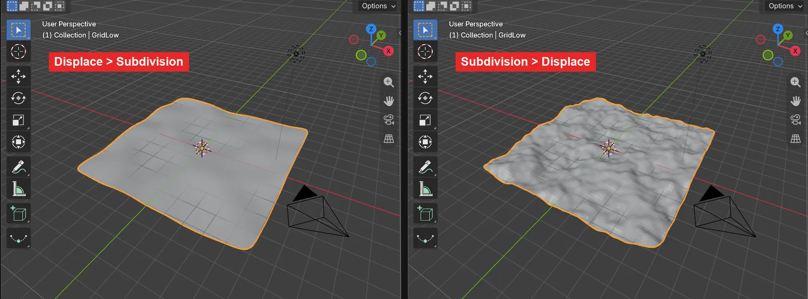 Figure 8. Left Displace then Subdivision, right Subdivision then Displace (Blender screenshot)
Modifiers are calculated from top to bottom. With Displace first, only 121 points read the pattern and move, and Subdivision just rounds off that rough shape. With Subdivision first, the points are added first, and then all of them read the pattern. Put modifiers that add points above Displace.
5-2. Order mistakes from this series
| Pair | Correct order (top > bottom) | If reversed | Covered in |
|---|---|---|---|
| Subdivision Surface, Displace | Subdivision > Displace | Too few points to read the pattern, so bumps get blurred | This guide, section 5-1 |
| Array (Legacy), Curve | Array > Curve | Only one piece bends, and copies sit scattered with the same tilt | Curve modifier, section 4-3 |
| Screw, Solidify | Screw > Solidify | Thickness is given to a line with no faces yet, so the rim of the opening is not closed | Screw modifier, section 6 |
| Displace, Shrinkwrap (on another object) | The ground (Displace) is finished first | Not an order problem. If you turn off the ground's modifier, the road sticks to flat ground | This guide, section 6 |
If you get confused, remember the order "make the shape > add points > move points > thickness and finishing". It is not a rule without exceptions, but when a result looks wrong, trying a different order first is usually the fastest way to find the cause.
When you are done, delete the 10 by 10 grid with X > Delete and show the hidden 100 by 100 grid again with Alt+H.
6. Stick a road strip to the ground with Shrinkwrap
Starting point: the 100 by 100 ground from section 3 (Displace, Clouds Size 1.5, Strength 1).
Follow along (make the road strip):
- Press
Shift+A> Mesh > Grid and set X and Y Subdivisions to4and Size to1 m. Rename itRoad. - Press
Tab>A, then make a strip 0.8 m wide and 8 m long withS>X>0.8>EnterandS>Y>8>Enter. - Lift it above the ground with
G>Z>1.5>Enter, then pressTabto leave.
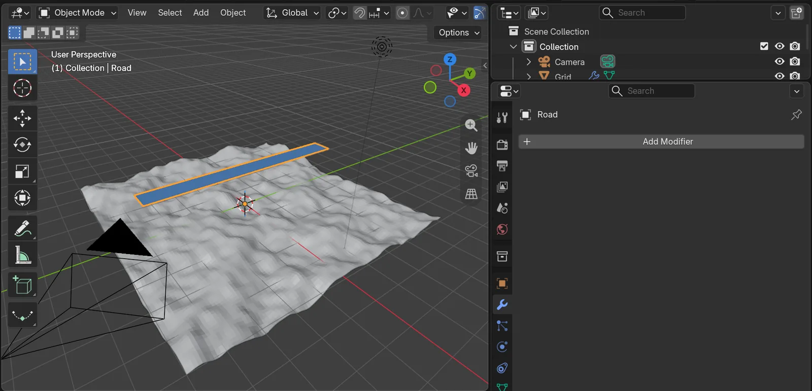 Figure 9. A flat road strip floating above the ground (Blender screenshot)
Follow along (stick it on):
- With the road strip selected, add Add Modifier > Deform > Shrinkwrap.
- Choose
Grid(the ground) in the Target field.
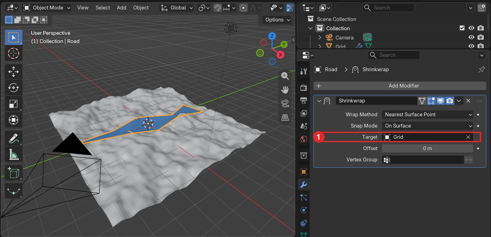 Figure 10. 1: Target: Grid. A road strip with few points sticks to the ground in only a few places (Blender screenshot)
The road strip has settled onto the ground. But it cannot follow the small bumps and is bent into a few large panels. Like Displace, Shrinkwrap moves points. With only 25 points, only those 25 places stick to the ground, and the faces between them stay flat.
If the ground you chose as Target has a Displace modifier, Shrinkwrap sticks to the bumpy ground with Displace applied. If you turn off the ground's Displace, the road sticks to a flat floor.
- Select the road strip, press
Tab>A, and choose Edge > Subdivide. In the Subdivide panel at the bottom left, set Number of Cuts to12, then pressTabto leave.
7. Nearest Surface Point and Project
Starting point: the subdivided road strip from the previous section (Shrinkwrap, Target Grid).
With more points, the road strip follows the bumps of the ground. But, as on the left of Figure 11, the edges of the road get jagged.
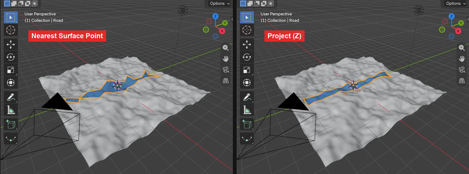 Figure 11. Left Wrap Method Nearest Surface Point (default), right Project (Z axis, both directions) (Blender screenshot)
The default, Nearest Surface Point, moves each point to "the closest point on the ground's surface". On a slope, the closest point is not straight below but off to the side, so points slide sideways and the road's shape gets distorted. For things whose shape seen from above must stay the same, like roads and puddles, use Project to drop them straight down.
Follow along:
- Change Wrap Method to
Project. - Under Axis, turn on
Z. - Turn on both Negative and Positive. By default only Positive is on, so it only searches upward. With both on, it sticks to whichever surface is closer, above or below.
- Set Offset to
0.05.
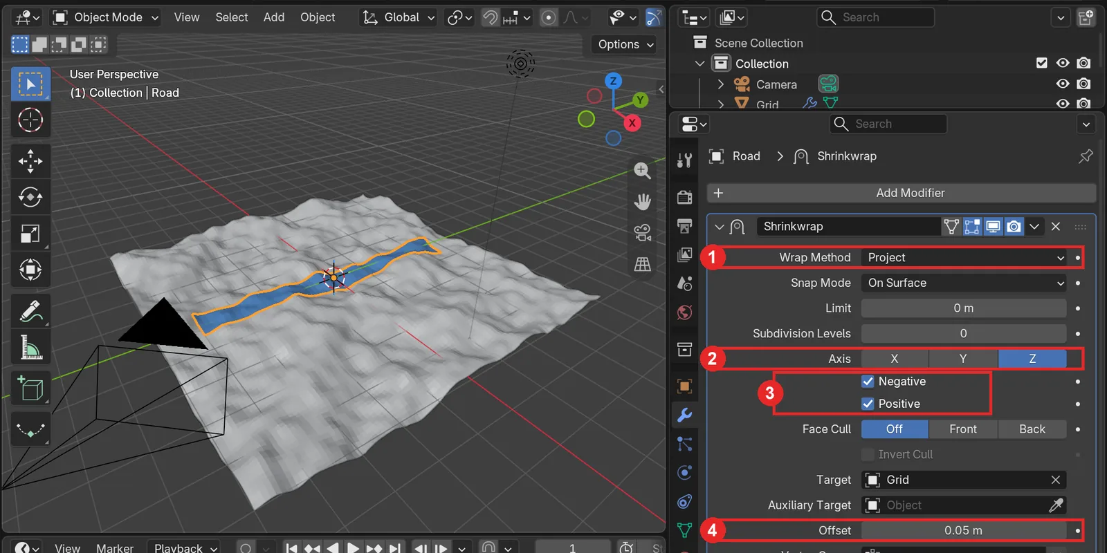 Figure 12. 1: Wrap Method: Project 2: Axis Z 3: Negative and Positive 4: Offset 0.05 m (Blender screenshot)
Offset is the distance to keep from the surface. At 0, the road's faces and the ground's faces sit at the same height, and the two can flicker through each other in the viewport or in renders. Lifting it a tiny bit keeps the road on top.
| Wrap Method | Where it moves points | Good for |
|---|---|---|
| Nearest Surface Point (default) | The closest point on the surface | Wrapping from all sides, like fitting clothes to a body |
| Project | Where a ray along the chosen axis hits | Things placed from above, like roads, puddles, floor decorations |
| Nearest Vertex | The closest point of the target | Matching exactly to the target's points (no Snap Mode) |
| Target Normal Project | Like Nearest Surface Point, but smoother | When you need a smooth result. Much slower |
With Project, points that hit no surface stay where they are. If the end of the road goes past the edge of the ground, only that part floats, so keep the road strip inside the ground.
Practice
- Instead of Clouds in section 3, change Type to
Voronoiand see what kind of ground you get. - Change the ground's Strength to
-1. Check how hills and valleys change, and whether the road strip follows. - Raise the road strip's Offset to
0.3. Check that the road still follows the ground but lifts up as a whole.
Common mistakes and fixes
| Symptom | Cause | Fix |
|---|---|---|
| The whole panel floated up after adding Displace | The texture is empty, so every point reads as white (1.0) | Make a texture with New and choose a Type (sections 2 and 3) |
| The texture exists but there is no pattern | Its first type is Image or Movie | Change Type to Clouds or another type in the Texture tab |
| The ground looks like a few angular panels | Too few points | More grid squares, or put Subdivision above Displace (sections 4-2 and 5-1) |
| The bumps are too small | Clouds Size is small | Raise Size (section 3) |
| The road cuts through the ground | The road strip has too few points | Split the road strip with Subdivide (section 6) |
| The road edges are jagged | Nearest Surface Point moves points sideways | Project + Axis Z (section 7) |
| The road does not move after switching to Project | No axis chosen, or only Positive is on so it searches upward only | Axis Z, turn on both Negative and Positive |
| Road and ground flicker through each other | The two surfaces overlap at the same height | Give Offset a small value |
Summary
Use Displace on a panel with many points, always pick a texture and set the bump size with Size, and put modifiers that add points above it. For Shrinkwrap, pick a Target, use Project + Z for things placed from above, and add a small Offset.
Pick other modifiers from Every Blender modifier in one list.
Previous: Curve modifier with Array · Whole series: Every Blender modifier in one list
References
- Blender 5.2 Manual: Displace Modifier
- Blender 5.2 Manual: Shrinkwrap Modifier
- Blender 5.2 Manual: Modifiers Introduction (stack order)
- Read next: Curve modifier with Array, Screw modifier, Building low-poly nature scenes with Poly Nature, Polygons and topology
- Shortcuts: Blender 5.2.1 default (Blender) keymap
- Image license: screenshots of Blender taken by AZTechnology. Blender license: blender.org/about/license